

Question: Question: Problem StatementThe Figure 1 below shows an electric motor driving a machine by means of three straight tooth spur gears required to have 1
Question: Problem StatementThe Figure below shows an electric motor driving a machine by means of three straight tooth spur gears required to have and teeth with a diametral pitch of An idler gear is used to facilitate the smooth transmission of motion between gears and ensure that the output shaft rotates in the desired direction without changing
Problem Statement
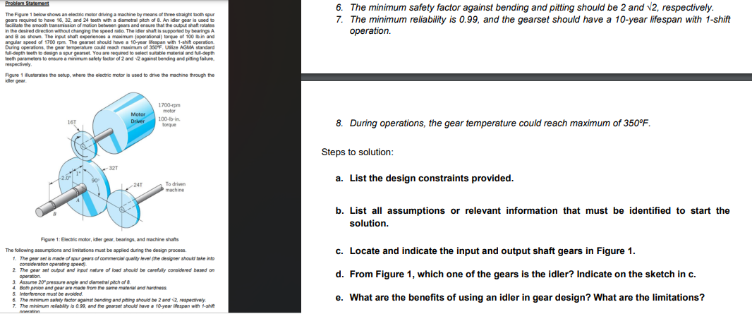
The Figure below shows an electric motor driving a machine by means of three straight tooth spur gears required to have and teeth with a diametral pitch of An idler gear is used to facilitate the smooth transmission of motion between gears and ensure that the output shaft rotates in the desired direction without changing the speed ratio. The idler shaft is supported by bearings A and B as shown. The input shaft experiences a maximum operationaltorque of lbin and angular speed of rpmThe gearset should have a year lifespan with shift operation. During operations, the gear temperature could reach maximum of FUtilize AGMA standard fulldepth teeth to design a spur gearset. You are required to select suitable material and fulldepth teeth parameters to ensure a minimum safety factor of and against bending and pitting failure, respectively.
Figure illusterates the setup, where the electric motor is used to drive the machine through the idler gear.
Figure : Electric motor, idler gear, bearings, and machine shafts.
The following assumptions and limitations must be applied during the design process.
The gear set is made of spur gears of commercial quality level the designer should take into consideration operating speed
The gear set output and input nature of load should be carefully considered based on operation.
Assume pressure angle and diametral pitch of
Both pinion and gear are made from the same material and hardness.
Interference must be avoided.
The minimum safety factor against bending and pitting should be and respectively
The minimum reliability is and the gearset should have a year lifespan with shift operation.
fDraw the free body diagram showing forces acting on the pinion, idler and gear. Hint: Refer to Shigley Exfor typical sketches
gEstimate the pinion, idler and gear diameters:
hEstimate the required gear unit enclosure spacing by calculating center distance, volume, and deciding accordingly.
The minimum safety factor against bending and pitting should be and sqrt respectively.
The minimum reliability is and the gearset should have a year lifespan with shift operation.
During operations, the gear temperature could reach maximum of circmathrmF
Steps to solution:
a List the design constraints provided.
b List all assumptions or relevant information that must be identified to start the solution.
c Locate and indicate the input and output shaft gears in Figure
d From Figure which one of the gears is the idler? Indicate on the sketch in c
What are the benefits of using an idler in gear design? What are the limitations
Step by Step Solution
There are 3 Steps involved in it
1 Expert Approved Answer
Step: 1 Unlock

Question Has Been Solved by an Expert!
Get step-by-step solutions from verified subject matter experts
Step: 2 Unlock
Step: 3 Unlock