

Question: In the circuit shown in the figure below, C1=18uF, C2=33F, C3=11pF, and a voltage Vab-10V is applied accross points a and b. After C1
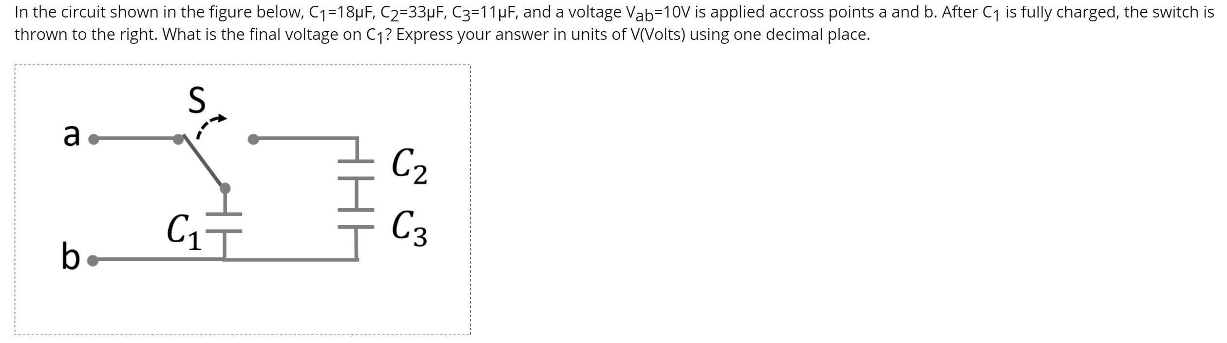
In the circuit shown in the figure below, C1=18uF, C2=33F, C3=11pF, and a voltage Vab-10V is applied accross points a and b. After C1 is fully charged, the switch is thrown to the right. What is the final voltage on C1? Express your answer in units of V(Volts) using one decimal place. a- C2 C3 b
Step by Step Solution
★★★★★
3.30 Rating (144 Votes )
There are 3 Steps involved in it
1 Expert Approved Answer
Step: 1 Unlock

69 V Explanation The charges on capacitors 2 and 3 are the same so these capacitors may be replaced ... View full answer
Question Has Been Solved by an Expert!
Get step-by-step solutions from verified subject matter experts
Step: 2 Unlock
Step: 3 Unlock