

Question: Reading Materials: (1) AISC 360 specifications: Chapter F in AISC Manual Part 16; (2) AISC ASIC Part 3: Flexural Members; and (3) Class notes
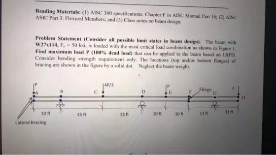
Reading Materials: (1) AISC 360 specifications: Chapter F in AISC Manual Part 16; (2) AISC ASIC Part 3: Flexural Members; and (3) Class notes on beam design. Problem Statement (Consider all possible limit states in beam design). The beam with W27x114, F, - 50 ksi, is loaded with the most critical load combination as shown in Figure 1. Find maximum load P (100% dead load) that can be applied to the beam based on LRFD. Consider bending strength requirement only. The locations (top and/or bottom flanges) of bracing are shown in the figure by a solid dot. Neglect the beam weight. Hinge 10 ft 15 ft 15 ft 10 ft 10 ft 11 t 11 t Lateral bracing
Step by Step Solution
3.41 Rating (145 Votes )
There are 3 Steps involved in it
W 2 7X114 Sy 227 in3 Fle y 50 ksi F BD1 4P ... View full answer

Get step-by-step solutions from verified subject matter experts