

Question: Real - Time Parity Bit Generator ( PG 4 ) Design PG 4 Block Diagram and Description. The block diagram for PG 4 is denisted
RealTime Parity Bit Generator PG Design
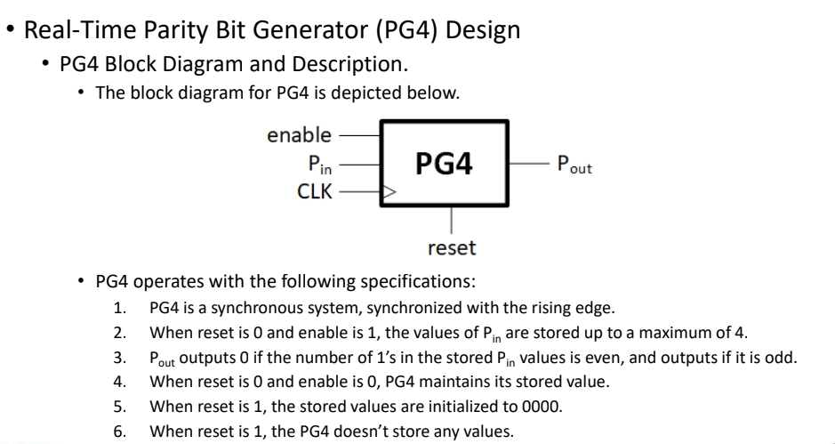
PG Block Diagram and Description.
The block diagram for PG is denisted helow.
PG operates with the following specifications:
PG is a synchronous system, synchronized with the rising edge.
When reset is and enable is the values of are stored up to a maximum of
outputs if the number of s in the stored values is even, and outputs if it is odd.
When reset is and enable is maintains its stored value.
When reset is the stored values are initialized to
When reset is the PG doesn't store any values.
Step by Step Solution
There are 3 Steps involved in it
1 Expert Approved Answer
Step: 1 Unlock

Question Has Been Solved by an Expert!
Get step-by-step solutions from verified subject matter experts
Step: 2 Unlock
Step: 3 Unlock