

Question: Refer to the continuous T - beam shown below. Image ( a ) shows the cross - section of the continuous T - beam. Image
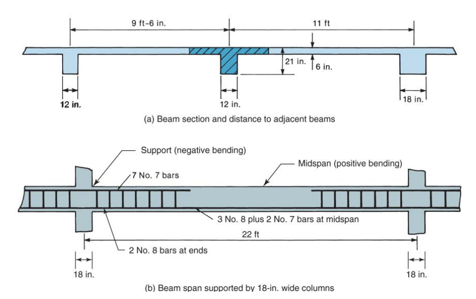
Refer to the continuous Tbeam shown below. Image a shows the crosssection of the continuous Tbeam. Image b shows the span of the Tbeam.a Beam section and distance to adjacent beams
Compute the effective flange width for the Tbeam in the middle of image a You should only use the clear span, so you need to subtract out half of the column width on each end to get the clear span and use that value for l
At midspan, there are two layers of tension rebar: #s in the bottom layer and #s in the layer above. Assume minimum rebar spacing is satisfied. If the concrete has a compressive strength fc of psi, the rebar is Gr and there is a cover, what is the design moment capacity Phi Mn for the Tbeam in the middle of image a at midspan ie where there is positive bending only and no compression reinforcement
Step by Step Solution
There are 3 Steps involved in it
1 Expert Approved Answer
Step: 1 Unlock

Question Has Been Solved by an Expert!
Get step-by-step solutions from verified subject matter experts
Step: 2 Unlock
Step: 3 Unlock