

Question: a) The continuous displacement along a truss element is assumed to be linear u(s) a+bs, where s is the distance along the element. At
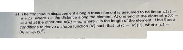
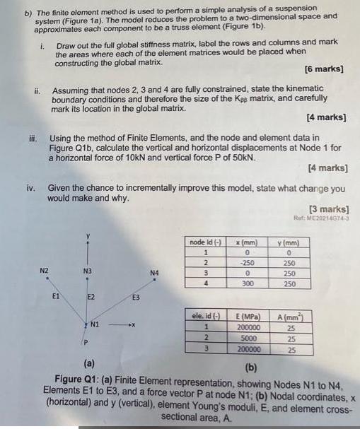
a) The continuous displacement along a truss element is assumed to be linear u(s) a+bs, where s is the distance along the element. At one end of the element z(0) u, and at the other end u(L) =uy, where L is the length of the element. Use these conditions to derive a shape function [W] such that u(s) = [N]{u), where (u) (uvu, v). b) The finite element method is used to perform a simple analysis of a suspension system (Figure 1a). The model reduces the problem to a two-dimensional space and approximates each component to be a truss element (Figure 1b). 1. [6 marks] ii. Assuming that nodes 2, 3 and 4 are fully constrained, state the kinematic boundary conditions and therefore the size of the Kee matrix, and carefully mark its location in the global matrix. iii. Draw out the full global stiffness matrix, label the rows and columns and mark the areas where each of the element matrices would be placed when constructing the global matrix. [4 marks] Using the method of Finite Elements, and the node and element data in Figure Q1b, calculate the vertical and horizontal displacements at Node 1 for a horizontal force of 10kN and vertical force P of 50KN. [4 marks] iv. Given the chance to incrementally improve this model, state what change you would make and why. N2 E1 N3 E2 N1 E3 N4 node Id (-) 1 2 3 4 ele. id (-) 1 2 3 x (mm) 0 -250 0 300 E (MPa) 200000 5000 200000 [3 marks] Ref: ME20214074-3 y (mm) 0 250 250 250 A (mm) 25 25 25 (b) (a) Figure Q1: (a) Finite Element representation, showing Nodes N1 to N4, Elements E1 to E3, and a force vector P at node N1; (b) Nodal coordinates, x (horizontal) and y (vertical), element Young's moduli, E, and element cross- sectional area, A.
Step by Step Solution
3.49 Rating (169 Votes )
There are 3 Steps involved in it
To derive the shape function N for the given truss element we can use the linear displacement functi... View full answer

Get step-by-step solutions from verified subject matter experts