

Question: Required information Problem 0 5 . 0 7 6 - Calculating the minimum diameter of a shaft Skip to question The gure shows a shaft
Required information
Problem Calculating the minimum diameter of a shaft
Skip to question
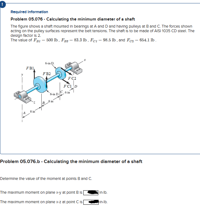
The gure shows a shaft mounted in bearings at A and D and having pulleys at B and C The forces shown acting on the pulley surfaces represent the belt tensions. The shaft is to be made of AISI CD steel. The design factor is
The value of FBlbFBlb FBlbFBlb FClbFClb and FClbFClb
The left end of the shaft is labeled as A and acts as an origin. The shaft is along the xaxis. The vertical axis is yaxis. A pulley is mounted at point B at a distance of inches from point A Forces F B and F B act on the pulley in the upward direction, along the y axis. The diameter of the pulley is inches. The second pulley is mounted at point C inches from point B The forces labeled F C and F C act on it in the opposite direction, along the z axis. The diameter of the pulley is inches. Point D is at the right end of the shaft and is at a distance of inches from point B
Problem b Calculating the minimum diameter of a shaft
Determine the value of the moment at points B and C
The maximummoment on plane xy at point Bis inlb
The maximummoment on plane xzat point C is inlb
Problem b Calculating the minimum diameter of a shaft
Determine the value of the moment at points B and C
The maximum moment on plane xy at point B is
Inlb
The maximum moment on plane xz at point C is
Inlb
Step by Step Solution
There are 3 Steps involved in it
1 Expert Approved Answer
Step: 1 Unlock

Question Has Been Solved by an Expert!
Get step-by-step solutions from verified subject matter experts
Step: 2 Unlock
Step: 3 Unlock