

Question: Resistive networks are well-represented by linear equations. Consider the DC circuit shown below: This problem can be converted into a system of simultaneous linear equations
Resistive networks are well-represented by linear equations. Consider the DC circuit shown below: 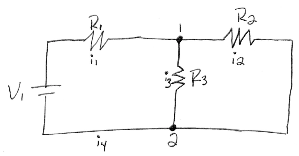 This problem can be converted into a system of simultaneous linear equations by applying Kirchhoff's law and Ohm's law. In circuit design, ii represents current (measured in amperes, A), V represents voltage (in volts, V), and R represents resistance (in ohms, ?). Kirchhoff's law states that the sum of the currents entering a node is equal to the sum of the currents leaving the node. Applying Kirchoff's law to nodes 1 and 2 respectively yields the equations
 (1)
(1)
 (2)
(2)
To apply Ohm's law, we can use two separate pathways through the circuit in going from the positive side of the DC power source to the negative side: the inner circuit and the outermost circuit. In both cases, the sum of the current times the resistance is equal to the applied voltage V1 The resulting equations are given as
 (3)
(3)
 (4)
(4)
For this particular system, V1 has a value of 100 V, R1 has a value of 10 ?, R2 has a value of 5 ?, and R3 has a value of 10 ?. The current values are the unknowns in this linear system of simultaneous linear equations. Analytically (i.e. with paper and pencil), put this system into the matrix form Ax=b, and use that result to enter the variables A and b into your program; you do not need to turn in your analytical work for determining what A and b are. Once you have determined what A and b are, solve this system using the matrix inverse. Print the values of the temperatures to the Command Window with labels and units; do not use a loop to automate the printing process.
In Ps V, 3 'Y 3 41 0 RW
Step by Step Solution
There are 3 Steps involved in it

Get step-by-step solutions from verified subject matter experts