

Question: Resistor's Color Code (Record four color bands) Coded Resistance () Measured Tolerance Maximum Coded (8) Resistance (2) (S) Minimum Coded Resistance Resistance (F) Resistor


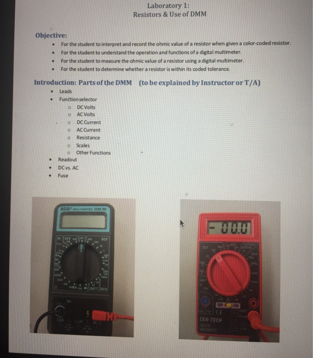

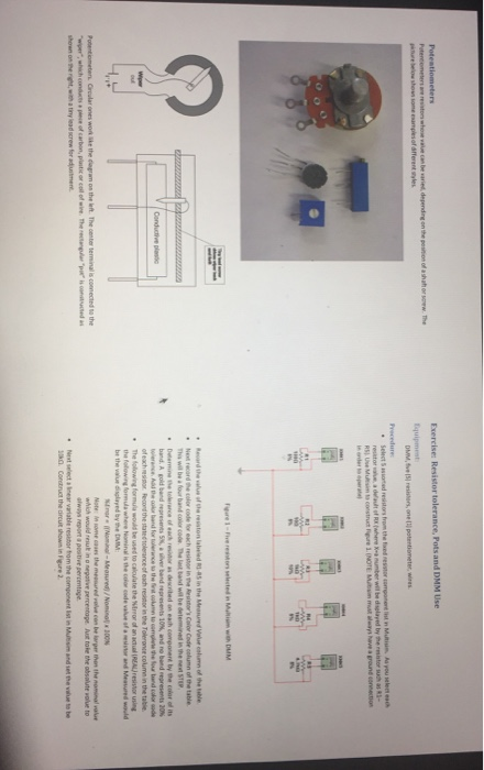
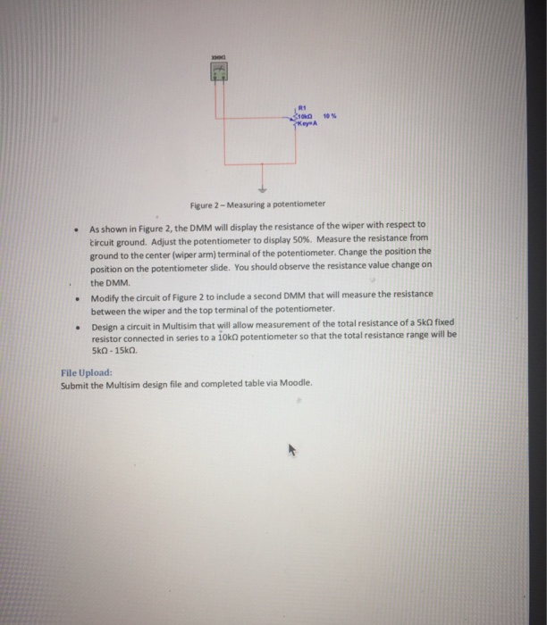
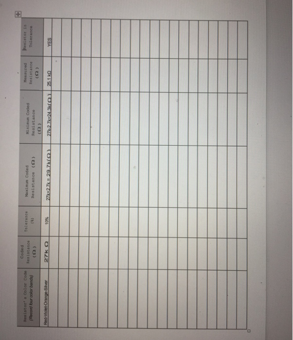
Resistor's Color Code (Record four color bands) Coded Resistance () Measured Tolerance Maximum Coded (8) Resistance (2) (S) Minimum Coded Resistance Resistance (F) Resistor in Tolerance Red-Violet-Orange-Silver 27k Q 10% 27k+2.7k 29.7k(Q) 27k 2.7k 24.3k) 25.1 kQ YES + R1 100 10% Key A . . Figure 2-Measuring a potentiometer As shown in Figure 2, the DMM will display the resistance of the wiper with respect to circuit ground. Adjust the potentiometer to display 50%. Measure the resistance from ground to the center (wiper arm) terminal of the potentiometer. Change the position the position on the potentiometer slide. You should observe the resistance value change on the DMM. Modify the circuit of Figure 2 to include a second DMM that will measure the resistance between the wiper and the top terminal of the potentiometer. Design a circuit in Multisim that will allow measurement of the total resistance of a SkQ fixed resistor connected in series to a 10k potentiometer so that the total resistance range will be 5kQ-15kQ. File Upload: Submit the Multisim design file and completed table via Moodle. Potentiometers Potentiometers are resistors whose value can be varied, depending on the position of a shaft or sew. The picture below shown some examples of different styles Exercise: Resistor tolerance, Pots and DMM Use Equipment DMM, five (5) resistors, one (1) potentiometer, wires Procedure Select Sassorted resistors from the fixed resistor component list in Multisim. As you select each resistor value, a default of RX (where X-a number will be displayed by the resistor such as R1- RS) Use Multisim to construct Figure 1. (NOTE: Multisim must always have a ground connection in onder to operat www 10 w www P Wiper Conductive plastic Potentiometers Circular ones work like the diagram on the left. The center terminal is connected to the "wiper, which conducts a piece of carbon, plastic or coll of wire. The rectangular "p" is constructed as shown on the right, with a tiny lead screw for adjustment. . " Figure 1-Five resistors selected in Multisim with DMM e table Record the value of the resiston labeled R-R5 in the Measured Value column of the table. Next record the color code for each resistor in the Resistor's Color Code column of t This will be a four band color code. The last band will be determined in the next STEP Determine the tolerance of each resistor as described on each component by the color of its band. A gold band represents 5%, a silver band represents 10%, and no band represents 20% tolerance. Add the color band for tolerance to the first column to complete the four band color code of each resistor. Record the stated tolerance of each resistor in the Tolerance column in the table. The S following formula would be used to calculate the Nirror of an actual (REAL) resistor using the following formula where Nominal is the color code value of a resistor and Measured would be the value displayed by the DMM Enor Nominal-Measured)/Nominal 300% Note: In some cases the measured velve can be larger then the nominal value which would result in a negative percentage. Just take the absolute value to always report a positive percentage Next select a linear variable resistor from the componert ist in Multisim and set the value to be 10k Construct the circuit shown in Figure 2. Laboratory 1: Resistors & Use of DMM Objective: For the student to interpret and record the ohmic value of a resistor when given a color-coded resistor. For the student to understand the operation and functions of a digital multimeter. For the student to measure the ohmic value of a resistor using a digital multimeter. For the student to determine whether a resistor is within its coded tolerance. Introduction: Parts of the DMM (to be explained by Instructor or T/A) . Leads . Functionselector o DC Volts AC Volts DC Current AC Current Resistance Scales o Other Functions . Readout DC vs. AC Fuse ECG MULTIMETER DM-50 10A DCV BATT OCA 00.0 OFF ON CE CEN-TECH DIGITAL MULTIMETER VONA DCA A voltmeter is designed to measure the voltage between any two points in a circuit, when the circuit is energired If the voltage to l measured is v12-v1-v2, then the black probe is placed on node 2 (corresponding to v2) and the red probe is placed on node 1 (corresponding to vi). Since the voltmeter is placed in parallel with i the circuit it potentially can disrupt circuit operation. Ideally, a voltmeter's resistance is infinite-in which there would be no change in circuit operation An ammeter is designed to measure current at a point in an energized crout. To take this reading the drout must be disconnected at the point of interest and the ammeter inserted in series with the crout that poin Again, the ammeter can potentially disrupt circuit operation Meally, an ammeter's resistance is zero-in which case there would be no change in circuit operation An ohmmeter is designed to measure the resistance of a device. To do so, the device must be disconnected from the circuit for else the resistance of the device in parallel with the circuit is measured). Two-wire and four-wire resistance measurement techniques are possible, as decovered in the laboratory exercise Breadboards and their use A breadboard also known as protoboard is a type of solderless electronic circuit building. You can build a electronic circuit on a breadboard without any soldering! Best of all it is reusable. Building or prototyping circuits on a breadboard is also known as 'breadboarding. The breadboard allows you to assemble circuits by placing components into the holes, officially called contact points but usually just points, which are connected internally in various patterns. You can find more at http://www.engineersgarage.com/insight/how-breadboard works Breadboards are usually divided into four sections, two outer sections and two inner sections. Each row of five sockets in the inner sections are electrically connected to each other (see the green lines in the next figure). The two outer sections of the breadboard are usually used exclusively for power. On many breadboards these sockets will be labeled with colors denoting positive voltage (usually red) and ground (black or blue). It is important to note that on many breadboards the power lines only run half the length of the board (as indicated in the next figure). You will need to run a wire between these two sections to send power to from one end to the other. There is nothing special about the outer sections of the breadboard that makes particularly suitable for power other than that they run most of the length of the board, but if you choose to use these rows for other things you may confuse others or even yourself, so it is good practice to use these for power only. Resistor Color Codes Resistor values can be determined by "reading the bands of color printed on the res ALCON OW 1508 Resistors of different wattages showing color code bands Bottom 0.25W. Color bands give resistance and tolerance. Gold tolerance band is /-5%, silver is +/- 10%. Read values by taking first two digits and multiply by 10" where d3 is the number represented by the third color band. Chart is below. For example the resistor in the middle is a 1W, 47x 10'0 or 470 resister. The one above it is 2W, 27 x 10'0 27000 or 2. 10000 100000] Potentiometers Potentiometers are resistors whose value can be varied, depending on the position of a shaft or sew. The picture below shown some examples of different styles Exercise: Resistor tolerance, Pots and DMM Use Equipment DMM, five (5) resistors, one (1) potentiometer, wires Procedure Select Sassorted resistors from the fixed resistor component list in Multisim. As you select each resistor value, a default of RX (where X-a number will be displayed by the resistor such as R1- RS) Use Multisim to construct Figure 1. (NOTE: Multisim must always have a ground connection in onder to operat www 10 w www P Wiper Conductive plastic Potentiometers Circular ones work like the diagram on the left. The center terminal is connected to the "wiper, which conducts a piece of carbon, plastic or coll of wire. The rectangular "p" is constructed as shown on the right, with a tiny lead screw for adjustment. . " Figure 1-Five resistors selected in Multisim with DMM e table Record the value of the resiston labeled R-R5 in the Measured Value column of the table. Next record the color code for each resistor in the Resistor's Color Code column of t This will be a four band color code. The last band will be determined in the next STEP Determine the tolerance of each resistor as described on each component by the color of its band. A gold band represents 5%, a silver band represents 10%, and no band represents 20% tolerance. Add the color band for tolerance to the first column to complete the four band color code of each resistor. Record the stated tolerance of each resistor in the Tolerance column in the table. The S following formula would be used to calculate the Nirror of an actual (REAL) resistor using the following formula where Nominal is the color code value of a resistor and Measured would be the value displayed by the DMM Enor Nominal-Measured)/Nominal 300% Note: In some cases the measured velve can be larger then the nominal value which would result in a negative percentage. Just take the absolute value to always report a positive percentage Next select a linear variable resistor from the componert ist in Multisim and set the value to be 10k Construct the circuit shown in Figure 2. R1 100 10% Key A . . Figure 2-Measuring a potentiometer As shown in Figure 2, the DMM will display the resistance of the wiper with respect to circuit ground. Adjust the potentiometer to display 50%. Measure the resistance from ground to the center (wiper arm) terminal of the potentiometer. Change the position the position on the potentiometer slide. You should observe the resistance value change on the DMM. Modify the circuit of Figure 2 to include a second DMM that will measure the resistance between the wiper and the top terminal of the potentiometer. Design a circuit in Multisim that will allow measurement of the total resistance of a SkQ fixed resistor connected in series to a 10k potentiometer so that the total resistance range will be 5kQ-15kQ. File Upload: Submit the Multisim design file and completed table via Moodle. Resistor's Color Code (Record four color bands) Coded Resistance () Measured Tolerance Maximum Coded (8) Resistance (2) (S) Minimum Coded Resistance Resistance (F) Resistor in Tolerance Red-Violet-Orange-Silver 27k Q 10% 27k+2.7k 29.7k(Q) 27k 2.7k 24.3k) 25.1 kQ YES + Resistor's Color Code (Record four color bands) Coded Resistance () Measured Tolerance Maximum Coded (8) Resistance (2) (S) Minimum Coded Resistance Resistance (F) Resistor in Tolerance Red-Violet-Orange-Silver 27k Q 10% 27k+2.7k 29.7k(Q) 27k 2.7k 24.3k) 25.1 kQ YES + R1 100 10% Key A . . Figure 2-Measuring a potentiometer As shown in Figure 2, the DMM will display the resistance of the wiper with respect to circuit ground. Adjust the potentiometer to display 50%. Measure the resistance from ground to the center (wiper arm) terminal of the potentiometer. Change the position the position on the potentiometer slide. You should observe the resistance value change on the DMM. Modify the circuit of Figure 2 to include a second DMM that will measure the resistance between the wiper and the top terminal of the potentiometer. Design a circuit in Multisim that will allow measurement of the total resistance of a SkQ fixed resistor connected in series to a 10k potentiometer so that the total resistance range will be 5kQ-15kQ. File Upload: Submit the Multisim design file and completed table via Moodle. Potentiometers Potentiometers are resistors whose value can be varied, depending on the position of a shaft or sew. The picture below shown some examples of different styles Exercise: Resistor tolerance, Pots and DMM Use Equipment DMM, five (5) resistors, one (1) potentiometer, wires Procedure Select Sassorted resistors from the fixed resistor component list in Multisim. As you select each resistor value, a default of RX (where X-a number will be displayed by the resistor such as R1- RS) Use Multisim to construct Figure 1. (NOTE: Multisim must always have a ground connection in onder to operat www 10 w www P Wiper Conductive plastic Potentiometers Circular ones work like the diagram on the left. The center terminal is connected to the "wiper, which conducts a piece of carbon, plastic or coll of wire. The rectangular "p" is constructed as shown on the right, with a tiny lead screw for adjustment. . " Figure 1-Five resistors selected in Multisim with DMM e table Record the value of the resiston labeled R-R5 in the Measured Value column of the table. Next record the color code for each resistor in the Resistor's Color Code column of t This will be a four band color code. The last band will be determined in the next STEP Determine the tolerance of each resistor as described on each component by the color of its band. A gold band represents 5%, a silver band represents 10%, and no band represents 20% tolerance. Add the color band for tolerance to the first column to complete the four band color code of each resistor. Record the stated tolerance of each resistor in the Tolerance column in the table. The S following formula would be used to calculate the Nirror of an actual (REAL) resistor using the following formula where Nominal is the color code value of a resistor and Measured would be the value displayed by the DMM Enor Nominal-Measured)/Nominal 300% Note: In some cases the measured velve can be larger then the nominal value which would result in a negative percentage. Just take the absolute value to always report a positive percentage Next select a linear variable resistor from the componert ist in Multisim and set the value to be 10k Construct the circuit shown in Figure 2. Laboratory 1: Resistors & Use of DMM Objective: For the student to interpret and record the ohmic value of a resistor when given a color-coded resistor. For the student to understand the operation and functions of a digital multimeter. For the student to measure the ohmic value of a resistor using a digital multimeter. For the student to determine whether a resistor is within its coded tolerance. Introduction: Parts of the DMM (to be explained by Instructor or T/A) . Leads . Functionselector o DC Volts AC Volts DC Current AC Current Resistance Scales o Other Functions . Readout DC vs. AC Fuse ECG MULTIMETER DM-50 10A DCV BATT OCA 00.0 OFF ON CE CEN-TECH DIGITAL MULTIMETER VONA DCA A voltmeter is designed to measure the voltage between any two points in a circuit, when the circuit is energired If the voltage to l measured is v12-v1-v2, then the black probe is placed on node 2 (corresponding to v2) and the red probe is placed on node 1 (corresponding to vi). Since the voltmeter is placed in parallel with i the circuit it potentially can disrupt circuit operation. Ideally, a voltmeter's resistance is infinite-in which there would be no change in circuit operation An ammeter is designed to measure current at a point in an energized crout. To take this reading the drout must be disconnected at the point of interest and the ammeter inserted in series with the crout that poin Again, the ammeter can potentially disrupt circuit operation Meally, an ammeter's resistance is zero-in which case there would be no change in circuit operation An ohmmeter is designed to measure the resistance of a device. To do so, the device must be disconnected from the circuit for else the resistance of the device in parallel with the circuit is measured). Two-wire and four-wire resistance measurement techniques are possible, as decovered in the laboratory exercise Breadboards and their use A breadboard also known as protoboard is a type of solderless electronic circuit building. You can build a electronic circuit on a breadboard without any soldering! Best of all it is reusable. Building or prototyping circuits on a breadboard is also known as 'breadboarding. The breadboard allows you to assemble circuits by placing components into the holes, officially called contact points but usually just points, which are connected internally in various patterns. You can find more at http://www.engineersgarage.com/insight/how-breadboard works Breadboards are usually divided into four sections, two outer sections and two inner sections. Each row of five sockets in the inner sections are electrically connected to each other (see the green lines in the next figure). The two outer sections of the breadboard are usually used exclusively for power. On many breadboards these sockets will be labeled with colors denoting positive voltage (usually red) and ground (black or blue). It is important to note that on many breadboards the power lines only run half the length of the board (as indicated in the next figure). You will need to run a wire between these two sections to send power to from one end to the other. There is nothing special about the outer sections of the breadboard that makes particularly suitable for power other than that they run most of the length of the board, but if you choose to use these rows for other things you may confuse others or even yourself, so it is good practice to use these for power only. Resistor Color Codes Resistor values can be determined by "reading the bands of color printed on the res ALCON OW 1508 Resistors of different wattages showing color code bands Bottom 0.25W. Color bands give resistance and tolerance. Gold tolerance band is /-5%, silver is +/- 10%. Read values by taking first two digits and multiply by 10" where d3 is the number represented by the third color band. Chart is below. For example the resistor in the middle is a 1W, 47x 10'0 or 470 resister. The one above it is 2W, 27 x 10'0 27000 or 2. 10000 100000] Potentiometers Potentiometers are resistors whose value can be varied, depending on the position of a shaft or sew. The picture below shown some examples of different styles Exercise: Resistor tolerance, Pots and DMM Use Equipment DMM, five (5) resistors, one (1) potentiometer, wires Procedure Select Sassorted resistors from the fixed resistor component list in Multisim. As you select each resistor value, a default of RX (where X-a number will be displayed by the resistor such as R1- RS) Use Multisim to construct Figure 1. (NOTE: Multisim must always have a ground connection in onder to operat www 10 w www P Wiper Conductive plastic Potentiometers Circular ones work like the diagram on the left. The center terminal is connected to the "wiper, which conducts a piece of carbon, plastic or coll of wire. The rectangular "p" is constructed as shown on the right, with a tiny lead screw for adjustment. . " Figure 1-Five resistors selected in Multisim with DMM e table Record the value of the resiston labeled R-R5 in the Measured Value column of the table. Next record the color code for each resistor in the Resistor's Color Code column of t This will be a four band color code. The last band will be determined in the next STEP Determine the tolerance of each resistor as described on each component by the color of its band. A gold band represents 5%, a silver band represents 10%, and no band represents 20% tolerance. Add the color band for tolerance to the first column to complete the four band color code of each resistor. Record the stated tolerance of each resistor in the Tolerance column in the table. The S following formula would be used to calculate the Nirror of an actual (REAL) resistor using the following formula where Nominal is the color code value of a resistor and Measured would be the value displayed by the DMM Enor Nominal-Measured)/Nominal 300% Note: In some cases the measured velve can be larger then the nominal value which would result in a negative percentage. Just take the absolute value to always report a positive percentage Next select a linear variable resistor from the componert ist in Multisim and set the value to be 10k Construct the circuit shown in Figure 2. R1 100 10% Key A . . Figure 2-Measuring a potentiometer As shown in Figure 2, the DMM will display the resistance of the wiper with respect to circuit ground. Adjust the potentiometer to display 50%. Measure the resistance from ground to the center (wiper arm) terminal of the potentiometer. Change the position the position on the potentiometer slide. You should observe the resistance value change on the DMM. Modify the circuit of Figure 2 to include a second DMM that will measure the resistance between the wiper and the top terminal of the potentiometer. Design a circuit in Multisim that will allow measurement of the total resistance of a SkQ fixed resistor connected in series to a 10k potentiometer so that the total resistance range will be 5kQ-15kQ. File Upload: Submit the Multisim design file and completed table via Moodle. Resistor's Color Code (Record four color bands) Coded Resistance () Measured Tolerance Maximum Coded (8) Resistance (2) (S) Minimum Coded Resistance Resistance (F) Resistor in Tolerance Red-Violet-Orange-Silver 27k Q 10% 27k+2.7k 29.7k(Q) 27k 2.7k 24.3k) 25.1 kQ YES +
Step by Step Solution
3.47 Rating (150 Votes )
There are 3 Steps involved in it
Here is the role of computational fluid dynamics CFD in process modeling Process Optimization via Nu... View full answer

Get step-by-step solutions from verified subject matter experts