

Question: Review Consider the beam shown in ( Figure 1 ) . EI is constant. Assume the support at B is a roller and A and
Review
Consider the beam shown in Figure EI is constant. Assume the support at is a roller and A and are fixed.
Part A
Determine the internal end moment: acting on span at A measured clockwise.
Express your answer in kilopoundfeet to three significant figures. Enter positive value if the moment is clockwise and negative value if the moment is counterclockwise.
View Available Hints
Correct
Here we learn how to determine the internal end moment acting on the span of a beam applying slopedeflection equations.
Part B
Determine the internal end moment acting on span at measured clockwise.
Express your answer in kilopoundfeet to three significant figures. Enter positive value if the moment is clockwise and negative value if the moment is counterclockwise.
View Available Hints
Previous Answers
Correct
Here we learn how to determine the internal end moment acting on the span of a beam apglying slopedeflection equations.
Figure
of
Part C
Determine the internal end moment acting on span at measured clockwise.
Express your answer in kilopoundfeet to three significant figures. Enter positive value if the moment is clockwise and negative value if the moment is counterclockwise.
View Available Hints
Previous Answers
Correct
Here we learn how to determine the internal end moment acting on the span of a beam applying slopedeflection equations.
Figure
of
Part D
Determine the internal end moment acting on span at measured clockwise.
Express your answer in kilopoundfeet to three significant figures. Enter positive value if the moment is clockwise and negative value if the moment is counterclockwise.
View Available Hints
Previous Answers
Correct
Here we learn how to determine the internal end moment acting on the span of a beam applying silopedeflection equations.
Part E
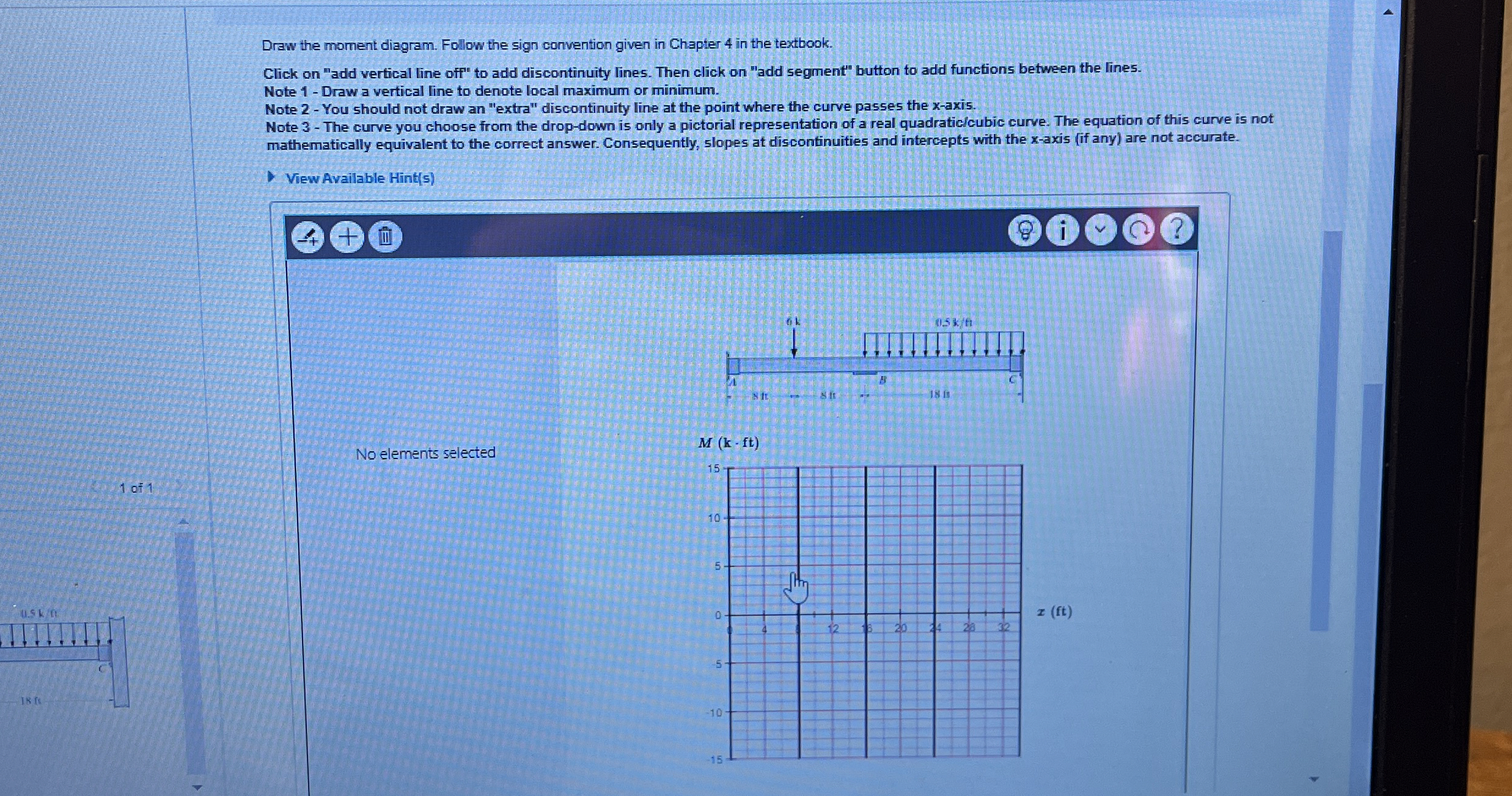
Draw the moment diagram. Follow the sign convention given in Chapter in the textbook.
Click on "add vertical line off" to add discontinuity lines. Then click on "add segment" button to add functions between the lines.
Note Draw a vertical line to denote local maximum or minimum.
Note You should not draw an "extra" discontinuity line at the point where the curve passes the x axis.
Note The curve you choose from the dropdown is only a pictorial representation of a real quadraticlcubic curve. The equation of this curve is not mathematically equivalent to the correct answer. Consequently, slopes at discontinuities and intercepts with the xaxis if any are not accurate.
View Available Hints
No elements selected
of
is Cl
Step by Step Solution
There are 3 Steps involved in it
1 Expert Approved Answer
Step: 1 Unlock

Question Has Been Solved by an Expert!
Get step-by-step solutions from verified subject matter experts
Step: 2 Unlock
Step: 3 Unlock