

Question: SE 1 1 0 A - Homework 8 Due: 8 : 1 5 pm May 3 1 , 2 0 2 4 Topic: Beam deflection,
SE A Homework Due: :pm May
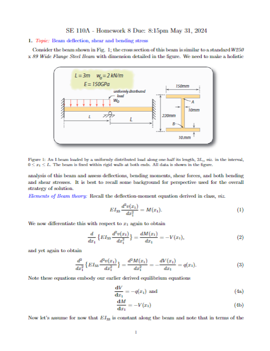
Topic: Beam deflection, shear and bending stress
Consider the beam shown in Fig. ; the croes section of this beam is similar to a standard
Wide Flange Steel Beam with dimension detailed in the figure. We need to make a holistic
Figure : An Ibeam loaded by a uniformly distributed losd along onehalf its length, viz in the interval,
and
The beam fixed within rigid walls both ende. All data shown the figure.
analysis this beam and assess deflections, bending moments, shear forces, and both bending
and shear stresser. best recall some background for perspective used for the overall
strategy solution.
Elements Beam theory: Recall the deflectionmoment equation derived class, viz.
now differentiate this with respect again obtain
and yet again obtain
Note these equations embody our earlier derived equilibrium equations
and
Now let's assuume for now that constant along the beam and note that terms the deflection we then have
The reason the last of these equations is written in the orientation it has is due to our stratepy
of solution that is adopted for this analysis. Note that eqs. ab are equations that give shesar
force and bending moment, respectively.
Let us define the tasks and procedure.
a Since the beam has no interior supports, write the expression for for the applied
loading using singularity functions such as and use it to construct eq Sc
b Integrate the order ordinary differential equation obtained from eqc and express
the varions integration constants along the way. At each integration besr in mind eqs. ab
and ask yourself if you can identify values for any such constants due to knowledge of either
moments or shear forces. Note, however, you have not yet performed any preanalysis via the
usaal methods of statics. Note that as you began you knew all information about the "applied
forces" and it is only the integration constants that require evaluation.
Iba Bearing in mind eqs. ab write down equations for shear force and bending moment as
soon as you can even though they may contain integration constants yet unknown.
c Invole all boundary conditions bes and evaluate all integration constants and construct
the shear foree and bending moment diagrams and sbetch them neatly. Identify ley points such
as maxima and minima along these diagrams. Plot those diagrams in terms of and ; you
will insert actual numbers later when evaluating streses. Note you should have boen esaluating
integration constants as you performed intogrations as scon as you werr able to
Id Evaluate the complete deflection curve, ie and sketch it in terms of the parameters,
and However, now put in mumbers and compute and indicate the actual maximum
deflection at the point it occurs.
e Evaluate the moment of inertia for this cross section and evaluate the maximum bending
stresses, both the extreme tensile and compressive bending stresses and indicate their locations
along the beam.
If Evaluate the maximum shear stress, and indicate its location. Also, evaluate the shear
stress in the web just below the points at the top and bottom of the beam where the web
meets the flanges; these points are labeled A and in Fig. Evaluate the shear stress at the
neutral axis of the beam. Perform all evaluations such as as original calculations without
appealing to canned formulas. Finally, evaluate the maximum shear stress in the flange and
indicate its location.
g Compute the ratio of maximum ie in magnitude shear stress to maximum bending
stress.
Step by Step Solution
There are 3 Steps involved in it
1 Expert Approved Answer
Step: 1 Unlock

Question Has Been Solved by an Expert!
Get step-by-step solutions from verified subject matter experts
Step: 2 Unlock
Step: 3 Unlock