

Question: The state of plane stresses at a point in a member is shown on the element in Figure Q5. 70 MPa 15 MPa T
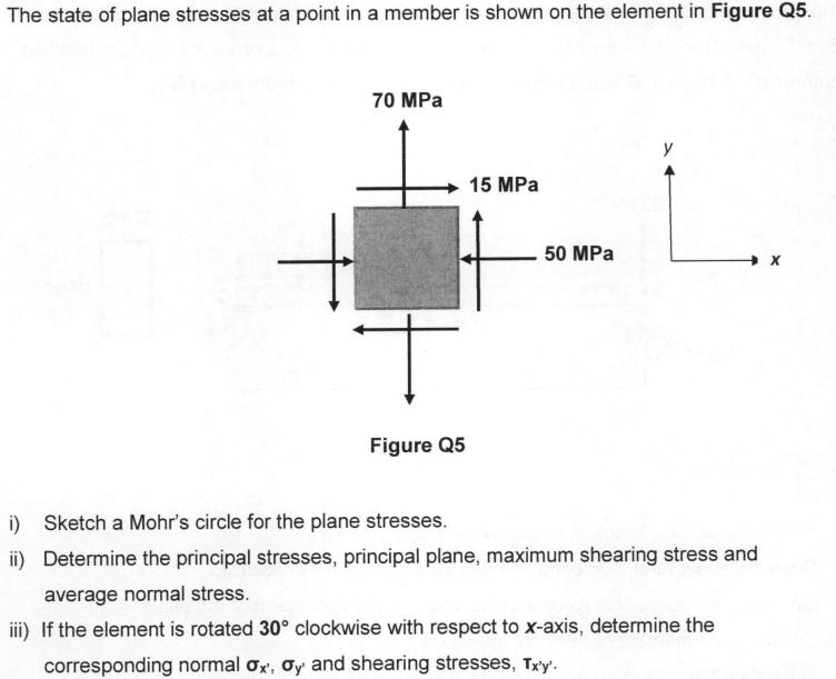
The state of plane stresses at a point in a member is shown on the element in Figure Q5. 70 MPa 15 MPa T Figure Q5 50 MPa i) Sketch a Mohr's circle for the plane stresses. ii) Determine the principal stresses, principal plane, maximum shearing stress and average normal stress. iii) If the element is rotated 30 clockwise with respect to x-axis, determine the corresponding normal ox, oy and shearing stresses, Tx'y'.
Step by Step Solution
3.31 Rating (148 Votes )
There are 3 Steps involved in it
i Sketch Mohrs circle x 70 MPa y 15 MPa xy 50 MPa R x y24 xy2 70 152... View full answer

Get step-by-step solutions from verified subject matter experts