

Question: Section 2 : DeviceNet Mapping Directions: Look at the following diagram depicting a DeviceNet network. There is a 1 7 5 6 - DNB module
Section : DeviceNet Mapping
Directions:
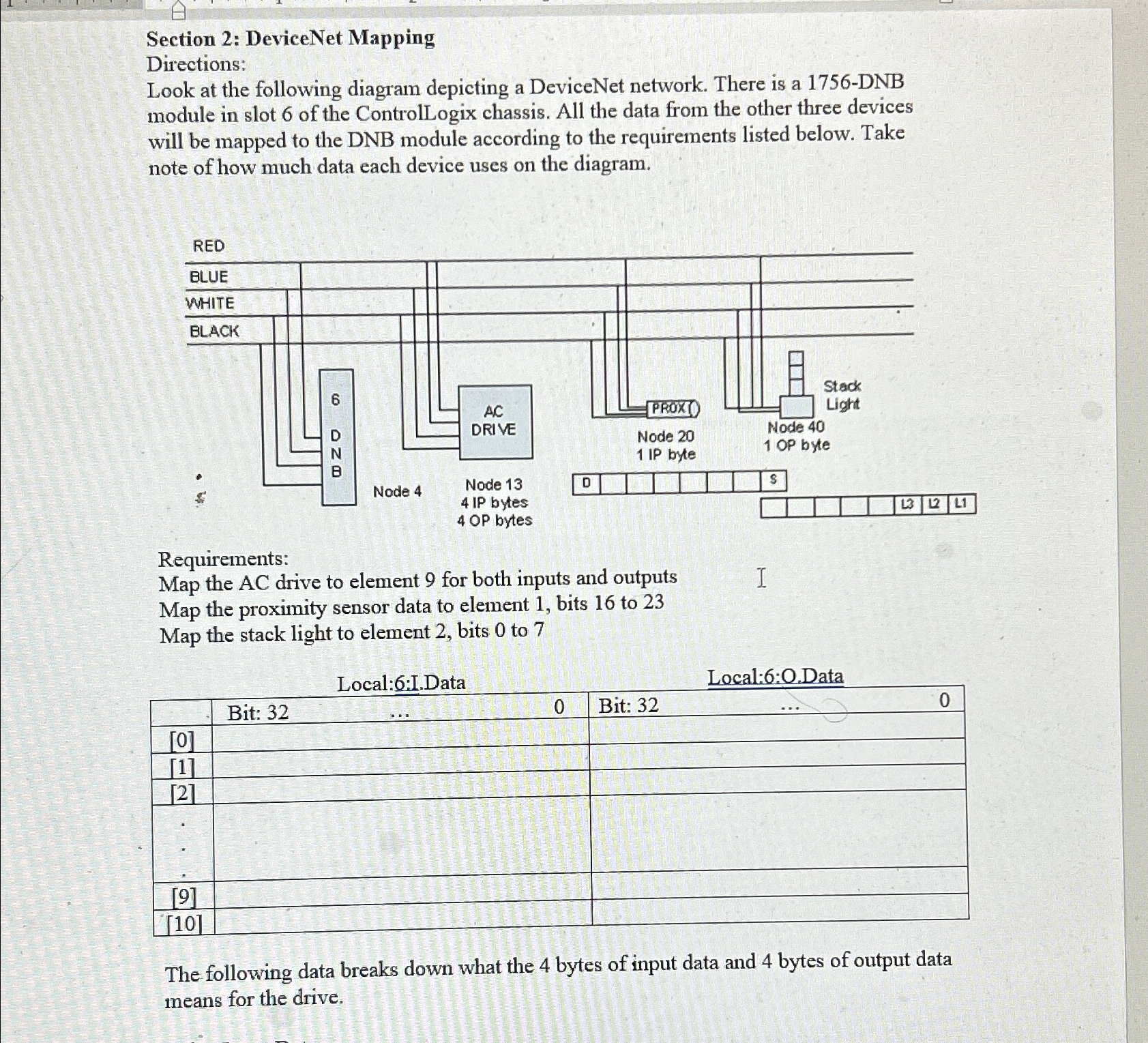
Look at the following diagram depicting a DeviceNet network. There is a DNB module in slot of the ControlLogix chassis. All the data from the other three devices will be mapped to the DNB module according to the requirements listed below. Take note of how much data each device uses on the diagram.
Requirements:
Map the AC drive to element for both inputs and outputs Map the proximity sensor data to element bits to Map the stack light to element bits to
Local::I.Data
Local::OData
tableBit: Bit:
The following data breaks down what the bytes of input data and bytes of output data means for the drive.
Step by Step Solution
There are 3 Steps involved in it
1 Expert Approved Answer
Step: 1 Unlock

Question Has Been Solved by an Expert!
Get step-by-step solutions from verified subject matter experts
Step: 2 Unlock
Step: 3 Unlock