

Question: Section 6 . 1 0 Problems 3 5 9 G 1 7 . Figure P 6 . G 1 7 shows a pump and piping
Section Problems
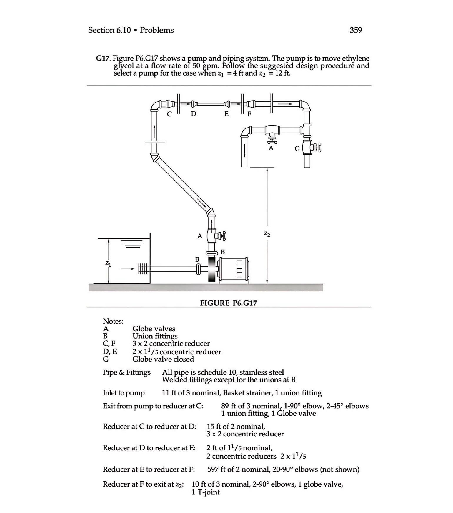
G Figure PG shows a pump and piping system. The pump is to move ethylene glycol at a flow rate of gpm Follow the suggested design procedure and select a pump for the case when and
FIGURE PG
Notes:
A Globe valves
B Union fittings
C F concentric reducer
D E concentric reducer
G Globe valve closed
Pipe & Fittings All pipe is schedule stainless steel Welded fittings except for the unions at
Inlet to pump of nominal, Basket strainer, union fitting
Exit from pump to reducer at C : of nominal, elbow, elbows union fitting, Globe valve
Reducer at C to reducer at D : ft of nominal, concentric reducer
Reducer at D to reducer at E: of nominal, concentric reducers
Reducer at E to reducer at F: of nominal, elbows not shown
Reducer at to exit at : of nominal, elbows, globe valve, Tjoint
Step by Step Solution
There are 3 Steps involved in it
1 Expert Approved Answer
Step: 1 Unlock

Question Has Been Solved by an Expert!
Get step-by-step solutions from verified subject matter experts
Step: 2 Unlock
Step: 3 Unlock