

Question: Show all steps and computations. 9 . 2 1 The Annulus and the Trapezoid The annulus shown below is cut from a planar metal sheet
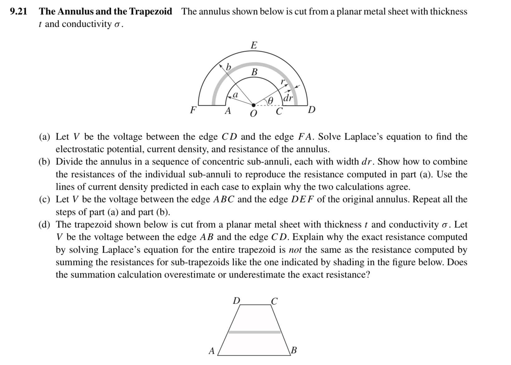
Show all steps and computations. The Annulus and the Trapezoid The annulus shown below is cut from a planar metal sheet with thickness t and conductivity sigma
a Let V be the voltage between the edge C D and the edge F A Solve Laplace's equation to find the electrostatic potential, current density, and resistance of the annulus.
b Divide the annulus in a sequence of concentric subannuli, each with width d r Show how to combine the resistances of the individual subannuli to reproduce the resistance computed in part a Use the lines of current density predicted in each case to explain why the two calculations agree.
c Let V be the voltage between the edge A B C and the edge D E F of the original annulus. Repeat all the steps of part a and part b
d The trapezoid shown below is cut from a planar metal sheet with thickness t and conductivity sigma Let V be the voltage between the edge A B and the edge C D Explain why the exact resistance computed by solving Laplace's equation for the entire trapezoid is not the same as the resistance computed by summing the resistances for subtrapezoids like the one indicated by shading in the figure below. Does the summation calculation overestimate or underestimate the exact resistance?
Step by Step Solution
There are 3 Steps involved in it
1 Expert Approved Answer
Step: 1 Unlock

Question Has Been Solved by an Expert!
Get step-by-step solutions from verified subject matter experts
Step: 2 Unlock
Step: 3 Unlock