

Question: Side surface Principal axis--- KEY E C V D 0 0.3 1 First digit 1 0.15 1.5 20.45 1.5 End surface D Part is
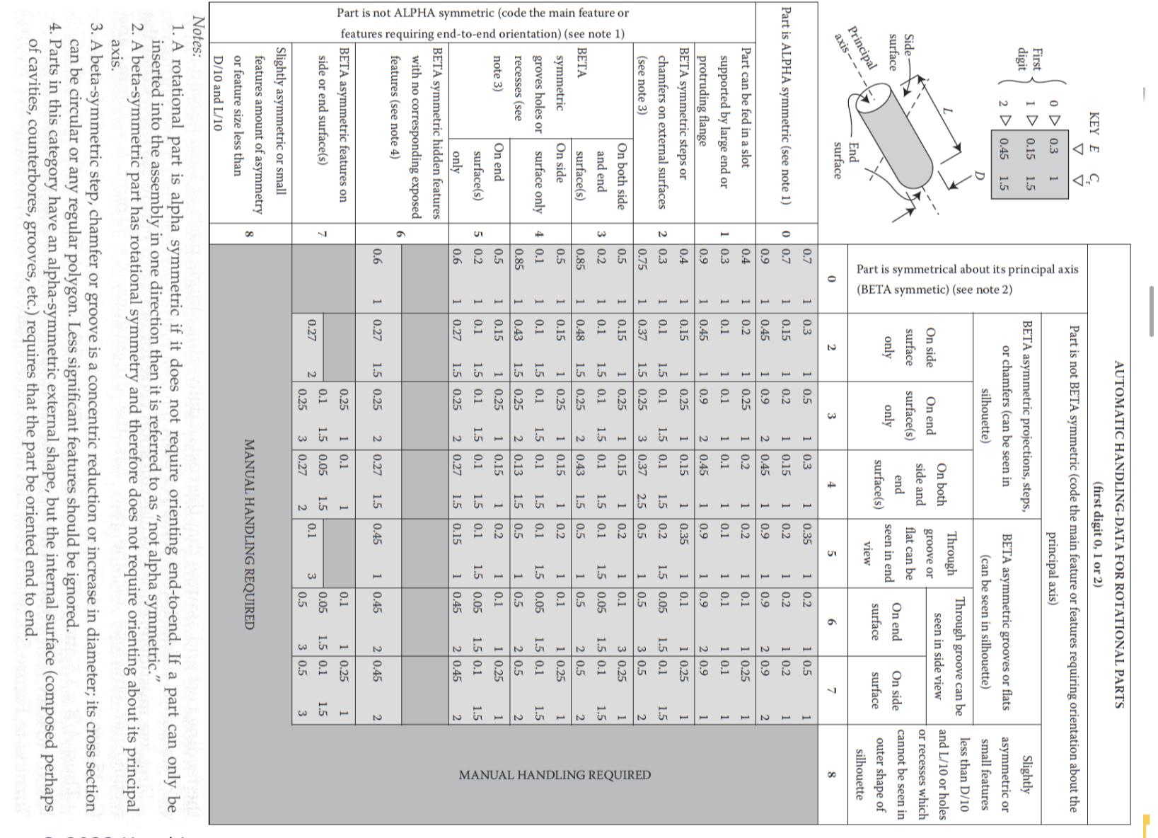
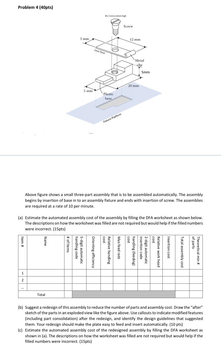
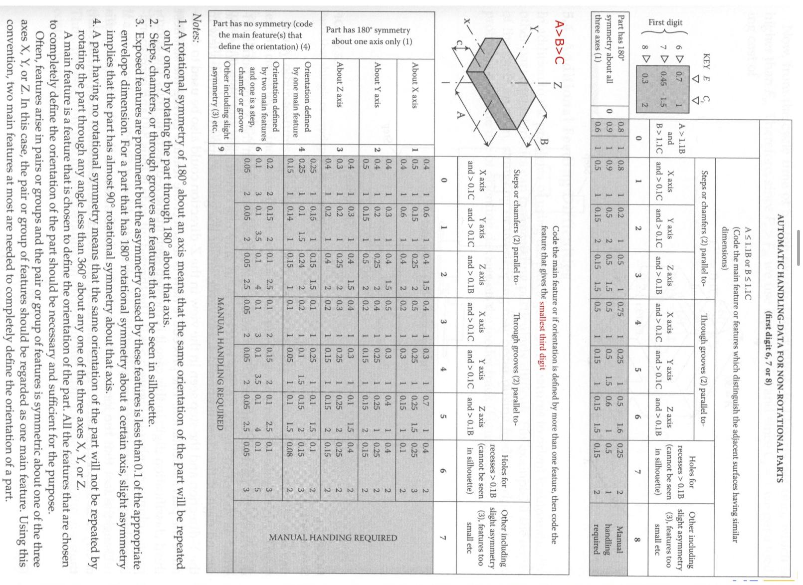
Side surface Principal axis--- KEY E C V "D 0 0.3 1 First digit 1 0.15 1.5 20.45 1.5 End surface D Part is symmetrical about its principal axis (BETA symmetic) (see note 2) AUTOMATIC HANDLING-DATA FOR ROTATIONAL PARTS (first digit 0, 1 or 2) Part is not BETA symmetric (code the main feature or features requiring orientation about the BETA asymmetric projections, steps, or chamfers (can be seen in silhouette) principal axis) BETA asymmetric grooves or flats (can be seen in silhouette) Through groove can be seen in side view On side On end surface(s) only On both side and end surface(s) Through groove or flat can be seen in end view On end surface On side surface surface only Slightly asymmetric or small features less than D/10 and L/10 or holes or recesses which cannot be seen in outer shape of silhouette 8 0 2 3 4 5 6 7 0.7 1 0.3 1 0.5 10.3 1 0.35 10.2 1 0.5 1 Part is ALPHA symmetric (see note 1) 0 0.7 1 0.15 1 0.2 1 0.15 1 0.2 1 0.2 1 0.2 1 0.9 1 0.45 1 0.9 2 0.45 1 0.9 1 0.9 2 0.9 2 Part can be fed in a slot 0.4 1 0.2 1 0.25 1 0.2 1 0.2 1 0.1 1 0.25 1 supported by large end or 1 0.3 1 0.1 1 0.1 1 0.1 1 0.1 1 0.1 1 0.1 1 protruding flange 0.9 1 0.45 1 0.9 2 0.45 1 0.9 1 0.9 2 0.9 1 BETA symmetric steps or 0.4 1 0.15 1 0.25 1 0.15 1 0.35 1 0.1 1 0.25 1 chamfers on external surfaces (see note 3) 2 0.3 1 0.1 1.5 0.1 1.5 0.1 1.5 0.2 1.5 0.05 1.5 0.1 1.5 0.75 Part is not ALPHA symmetric (code the main feature or features requiring end-to-end orientation) (see note 1) On both side 0.5 1 1 0.37 0.15 1.5 0.25 3 0.37 2.5 0.5 1 0.5 3 0.5 2 1 0.25 1 0.15 1 0.2 1 0.1 3 0.25 1 and end 3 0.2 1 0.1 1.5 0.1 1.5 0.1 1.5 0.1 1.5 0.05 1.5 0.1 1.5 BETA symmetric groves holes or recesses (see note 3) surface(s) 0.85 1 0.48 1.5 0.25 2 0.43 1.5 0.5 1 0.5 2 0.5 2 On side 0.5 1 0.15 1 0.25 1 0.15 1 0.2 1 0.1 1 0.25 1 surface only 4 0.1 1 0.1 1.5 0.1 1.5 0.1 1.5 0.1 1.5 0.05 1.5 0.1 1.5 0.85 1 0.43 1.5 0.25 2 0.13 1.5 0.5 1 0.5 2 0.5 2 On end 0.5 1 0.15 1 0.25 1 0.15 1 0.2 1 0.1 1 0.25 1 surface(s) only 5 0.2 1 0.1 1.5 0.1 1.5 0.1 1.5 10 0.1 1.5 0.05 1.5 0.1 1.5 0.6 1 0.27 1.5 0.25 2 0.27 1.5 0.15 1 0.45 2 0.45 2 BETA symmetric hidden features with no corresponding exposed 6 features (see note 4) 0.6 1 0.27 1.5 0.25 2 0.27 1.5 0.45 1 0.45 2 0.45 2 BETA asymmetric features on 0.25 side or end surface(s) 7 0.27 2 1 0.1 0.1 1.5 0.05 0.25 3 0.27 1 1.5 2 0.1 3 0.1 0.05 0.5 1 0.25 1 1.5 0.1 3 0.5 1.5 3 Slightly asymmetric or small features amount of asymmetry 8 MANUAL HANDLING REQUIRED or feature size less than Notes: D/10 and L/10 1. A rotational part is alpha symmetric if it does not require orienting end-to-end. If a part can only be inserted into the assembly in one direction then it is referred to as "not alpha symmetric." 2. A beta-symmetric part has rotational symmetry and therefore does not require orienting about its principal axis. 3. A beta-symmetric step, chamfer or groove is a concentric reduction or increase in diameter; its cross section can be circular or any regular polygon. Less significant features should be ignored. 4. Parts in this category have an alpha-symmetric external shape, but the internal surface (composed perhaps of cavities, counterbores, grooves, etc.) requires that the part be oriented end to end. MANUAL HANDLING REQUIRED Problem 4 (40pts) 02.5mmx 4mm high Screw 12 mm 5 mm Imm Thick Metal clip 5mm 5 mm Plastic base 20 mm Fixture Platform of parts Above figure shows a small three-part assembly that is to be assembled automatically. The assembly begins by insertion of base in to an assembly fixture and ends with insertion of screw. The assemblies are required at a rate of 10 per minute. (a) Estimate the automated assembly cost of the assembly by filling the DFA worksheet as shown below. The descriptions on how the worksheet was filled are not required but would help if the filled were incorrect. (15pts) numbers Item # 1 2 Name Total assembly cost Insertion cost. Relative work head cost handling (feeding) insertion code 2-digit automatic cost Max feed rate Relative handling cost Orienting efficiency. handling code 5-digit automatic # of Items Total Theoretical min # (b) Suggest a redesign of this assembly to reduce the number of parts and assembly cost. Draw the "after" sketch of the parts in an exploded view like the figure above. Use callouts to indicate modified features (including part consolidation) after the redesign, and identify the design guidelines that suggested them. Your redesign should make the plate easy to feed and insert automatically. (10 pts) (c) Estimate the automated assembly cost of the redesigned assembly by filling the DFA worksheet as shown in (a). The descriptions on how the worksheet was filled are not required but would help if the filled numbers were incorrect. (15pts) AUTOMATIC HANDLING-DATA FOR NON-ROTATIONAL PARTS (first digit 6, 7 or 8) A1.1B or B 1.1C (Code the main feature or features which distinguish the adjacent surfaces having similar dimensions) KEY E V Steps or chamfers (2) parallel to- Through grooves (2) parallel to- First digit 6 0.7 A> 1.1B 1 7 0.45 1.5 15 and X axis B>1.1C and > 0.1C Y axis and > 0.1C Z axis and > 0.1B X axis and> 0.1C Y axis and > 0.1C Z axis and > 0.1B Holes for recesses >0.1B (cannot be seen in silhouette) Other including slight asymmetry (3), features too small etc 8 0.3 2 0 1 2 3 4 5 6 7 8 Part has 180 0.8 0.8 1 0.2 1 0.5 1 0.75 symmetry about all three axes (1) 0 0.9 0.9 1 0.5 2 0.5 1.5 0.5 0.6 1 0.5 1 0.15 2 0.15 1.5 0.5 1 0.25 1 0.5 1 0.15 1 0.5 1.5 0.6 1 0.15 1.6 0.25 1 0.5 1.5 0.15 2 Manual 1 handling 2 required A>B>C Z B Code the main feature or if orientation is defined by more than one feature, then code the feature that gives the smallest third digit Steps or chamfers (2) parallel to- Through grooves (2) parallel to- X axis Y axis and >0.1C and > 0.1C Z axis and > 0.1B X axis Y axis and > 0.1C and > 0.1C Z axis and> 0.1B Holes for recesses > 0.1B (cannot be seen in silhouette) Other including slight asymmetry (3), features too small etc 0 1 2 3 4 5 6 7 About X axis 0.4 1 0.5 1 0.6 1 0.4 1.5 0.4 1 0.3 1 0.7 1 0.4 2 1 0.15 1 0.25 0.4 1 0.6 1 0.4 22 0.5 1 0.25 0.2 1 0.3 1 0.25 1.5 0.25 1 0.15 0.4 1 0.3 About Y axis 2 0.4 1 0.2 0.5 1 0.15 --- 1 0.4 1.5 0.5 1 0.3 1 0.4 1 0.25 2 0.4 1 0.25 1 0.25 0.5 2 0.2 1 0.15 1 0.15 0.4 1 0.3 1 0.4 1.5 0.4 1 0.3 1 0.1 1.5 About Z axis 3 0.3 1 0.2 1 0.25 2 0.3 1 0.25 1 0.25 0.4 1 0.2 1 0.4 2 0.2 1 0.15 1 0.15 22522 1 0.1 1 0.4 1 0.25 0.15 0.4 0.25 0.15 0.25 1 0.15 1 0.15 Orientation defined by one main feature 4 0.25 1 0.1 1.5 0.24 0.15 1 0.14 1 0.15 121 1.5 0.1 1 0.25 1 0.1 0.2 1 0.1 1.5 0.15 0.1 1 0.05 1 0.1 1.5 2 1.5 0.08 0.1 0.15 32222222232 Orientation defined 0.2 by two main features 6 0.1 0.05 232 0.15 2 0.1 0.1 3.5 0.1 4 0.1 2 0.05 2 0.05 2.5 2.5 0.1 MANUAL HANDING REQUIRED 2 0.15 3 0.1 2 0.1 3.5 0.1 0.05 2 0.05 2 0.05 2.5 0.05 22 2.5 0.1 4 0.1 353 Part has no symmetry (code the main feature(s) that define the orientation) (4) Part has 180 symmetry about one axis only (1) Notes: and one is a step, chamfer or groove Other including slight asymmetry (3) etc. 9 MANUAL HANDLING REQUIRED 1. A rotational symmetry of 180 about an axis means that the same orientation of the part will be repeated only once by rotating the part through 180 about that axis. 2. Steps, chamfers, or through grooves are features that can be seen in silhouette. 3. Exposed features are prominent but the asymmetry caused by these features is less than 0.1 of the appropriate envelope dimension. For a part that has 180 rotational symmetry about a certain axis, slight asymmetry implies that the part has almost 90 rotational symmetry about that axis. 4. A part having no rotational symmetry means that the same orientation of the part will not be repeated by rotating the part through any angle less than 360 about any one of the three axes X, Y, or Z. A main feature is a feature that is chosen to define the orientation of the part. All the features that are chosen to completely define the orientation of the part should be necessary and sufficient for the purpose. Often, features arise in pairs or groups and the pair or group of features is symmetric about one of the three axes X, Y, or Z. In this case, the pair or group of features should be regarded as one main feature. Using this convention, two main features at most are needed to completely define the orientation of a part.
Step by Step Solution
There are 3 Steps involved in it

Get step-by-step solutions from verified subject matter experts