

Question: SO Exercise 1 The picture below shows that the microcontroller can be connected to various input/output devices using the FOUR (4) connectors (J1, 12, 19,
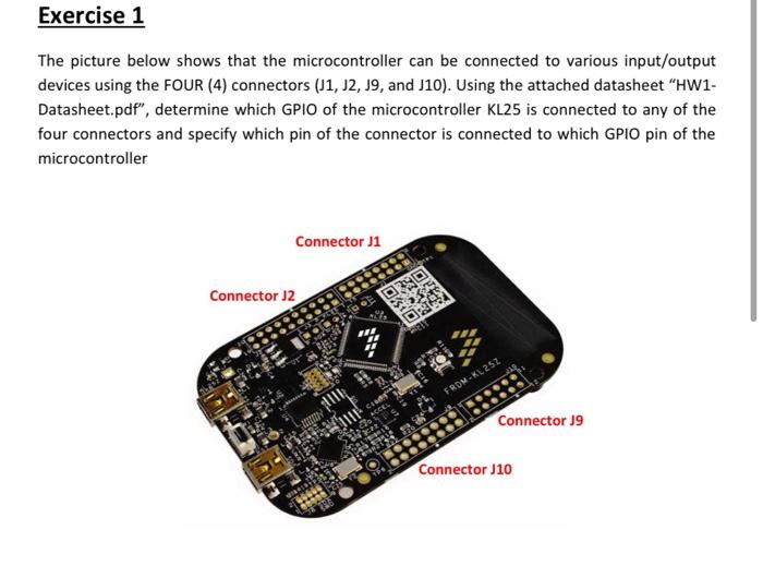
SO Exercise 1 The picture below shows that the microcontroller can be connected to various input/output devices using the FOUR (4) connectors (J1, 12, 19, and J10). Using the attached datasheet HW1- Datasheet.pdf", determine which GPIO of the microcontroller KL25 is connected to any of the four connectors and specify which pin of the connector is connected to which GPIO pin of the microcontroller Connector 1 Connector 2 a sto ORI o.101 FRDM-KL252 Connector J9 Oos O 06 J00000 Connector J10 SO Exercise 1 The picture below shows that the microcontroller can be connected to various input/output devices using the FOUR (4) connectors (J1, 12, 19, and J10). Using the attached datasheet HW1- Datasheet.pdf", determine which GPIO of the microcontroller KL25 is connected to any of the four connectors and specify which pin of the connector is connected to which GPIO pin of the microcontroller Connector 1 Connector 2 a sto ORI o.101 FRDM-KL252 Connector J9 Oos O 06 J00000 Connector J10
Step by Step Solution
There are 3 Steps involved in it

Get step-by-step solutions from verified subject matter experts