

Question: Two students (A and B) were asked to design good amplifier circuits using BJT. Although both opted for voltage divider configuration, their designs are
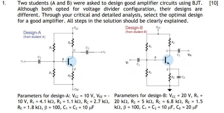
Two students (A and B) were asked to design good amplifier circuits using BJT. Although both opted for voltage divider configuration, their designs are different. Through your critical and detailed analysis, select the optimal design for a good amplifier. All steps in the solution should be clearly explained. 1. [10] Design-B (from student B) Vec Design-A (from student A) RC Vo B VEE Parameters for design-A: Vcc = 10 v, VEE = - Parameters for design-B: Vcc = 20 V, R, = 10 V, R, = 4.1 k2, R2 = 1.1 k2, Rc 2.7 k2, 20 k2, R2 = 5 kN, RC = 6.8 k2, RE = 1.5 RE = 1.8 k2, B = 100, C1 C2 10 F %3! k2, B = 100, C, C2 10 uF, CE = 20 F %3D %3! %3D %3D %3! %3! %3D
Step by Step Solution
3.48 Rating (155 Votes )
There are 3 Steps involved in it

Get step-by-step solutions from verified subject matter experts