

Question: SOLVE PART D PLEASE!!! 2 . ) ( 2 7 Points ) The shaft shown in the following figure is 2 0 0 mm long
SOLVE PART D PLEASE!!!
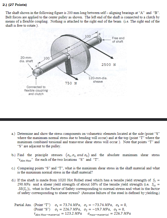
Points The shaft shown in the following figure is mm long between self aligning bearings at A and B Belt forces are applied to the center pulley as shown. The left end of the shaft is connected to a clutch by means of a flexible coupling. Nothing is attached to the right end of the beam ie The right end of the shaft is free to rotate. N N a Determine and show the stress components on volumetric elements located at the side point S where the maximum normal stress due to bending will occur and at the top point T where the maximum combined torsional and transverse shear stress will occur Note that points T and S are adjacent to the pulley. b Find the principle stresses and the absolute maximum shear stress for each of the two locations S and T c Comparing points S and T what is the maximum shear stress in the shaft material and what is the maximum normal stress in the shaft material? d If the shaft is made from Hot Rolled steel which has a tensile yield strength of and a shear yield strength of about of the tensile yield strength ie what is the Factor of Safety corresponding to normal stress and what is the factor of safety corresponding to shear stress? Assume failure of the steel is defined by yielding. Partial Ans. Point TPoint S
Step by Step Solution
There are 3 Steps involved in it
1 Expert Approved Answer
Step: 1 Unlock

Question Has Been Solved by an Expert!
Get step-by-step solutions from verified subject matter experts
Step: 2 Unlock
Step: 3 Unlock