

Question: Two reservoirs are linked by the system of pipes shown below in Figure Q4. The pipe properties are listed in Table Q4. The water
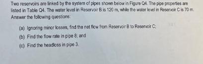
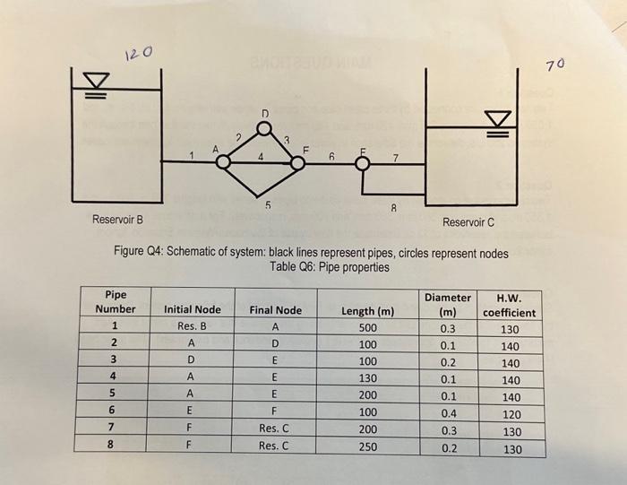
Two reservoirs are linked by the system of pipes shown below in Figure Q4. The pipe properties are listed in Table Q4. The water level in Reservoir B is 120 m, while the water level in Reservoir C is 70 m Answer the following questions: (a) Ignoring minor losses, find the net flow from Reservoir B to Reservoir C (b) Find the flow rate in pipe 8; and t (c) Find the headloss in pipe 3. Reservoir B Pipe Number 1 2 3 120 4 5 6 7 8 D Initial Node Res. B A D A A E F F 5 3 TI Figure Q4: Schematic of system: black lines represent pipes, circles represent nodes Table Q6: Pipe properties Final Node A D E E E F Res. C Res. C 6 7 8 Length (m) 500 100 100 130 200 100 200 250 Reservoir C Diameter (m) 0.3 0.1 All 0.2 0.1 0.1 0.4 0.3 0.2 H.W. coefficient 130 140 140 140 140 120 130 130 70
Step by Step Solution
There are 3 Steps involved in it
Answer To answer the questions we need to analyze the system of pipes and calculate the flow rates and head losses Lets go step by step a To find the ... View full answer

Get step-by-step solutions from verified subject matter experts