

Question: Solve these three questions components CL1 tpdl, teda -D -D 0 CL2 todz. tcd2 Fig. 7 Now, consider the circuit according to Fig. 7. It
 Solve these three questions
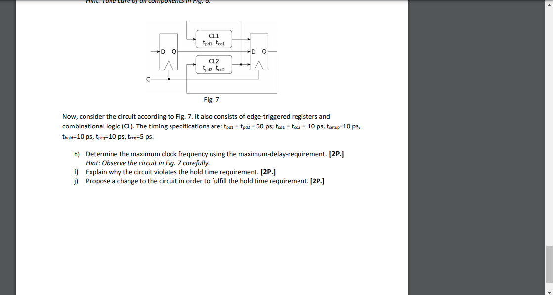
components CL1 tpdl, teda -D -D 0 CL2 todz. tcd2 Fig. 7 Now, consider the circuit according to Fig. 7. It also consists of edge-triggered registers and combinational logic (CL). The timing specifications are: tpdi = tpd2 = 50 ps; tedi = tcd2 = 10 ps, tsetup=10 ps, thold=10 ps, tpcq=10 ps, tecq=5 ps. h) Determine the maximum clock frequency using the maximum-delay-requirement. [2P.] Hint: Observe the circuit in Fig. 7 carefully. i) Explain why the circuit violates the hold time requirement. [2P.) j) Propose a change to the circuit in order to fulfill the hold time requirement. [2P.] components CL1 tpdl, teda -D -D 0 CL2 todz. tcd2 Fig. 7 Now, consider the circuit according to Fig. 7. It also consists of edge-triggered registers and combinational logic (CL). The timing specifications are: tpdi = tpd2 = 50 ps; tedi = tcd2 = 10 ps, tsetup=10 ps, thold=10 ps, tpcq=10 ps, tecq=5 ps. h) Determine the maximum clock frequency using the maximum-delay-requirement. [2P.] Hint: Observe the circuit in Fig. 7 carefully. i) Explain why the circuit violates the hold time requirement. [2P.) j) Propose a change to the circuit in order to fulfill the hold time requirement. [2P.]
Step by Step Solution
There are 3 Steps involved in it

Get step-by-step solutions from verified subject matter experts