

Question: solve through phase 1 and 7 Comprehensive Design Project: assigned: 0 3 / 0 9 / 2 0 2 4 . The structural system is
solve through phase and Comprehensive Design Project:
assigned:
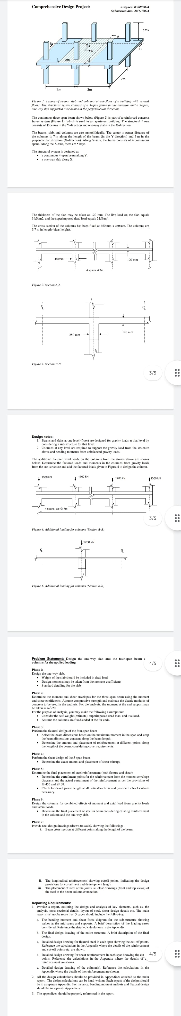
The structural system is designed as
a continuous span beam along Y
a oneway slab blong X
qquad
qquad
Figure : Section AA
::
Design notes:
Beans an
consideri
considering a substrucuture for that level.
Colounns at any level are for gravity loads at that level by
above and bending mon
:
qquad
Figure : Additional loading for columns Section BB
qquad
qquad
qquad
qquad
qquad
qquad
qquad
qquad
qquad
qquad
qquad
qquad
qquad
qquad
qquad
qquad
Phane
vdots:
ii The longitudinal reinforcement showing cutoff points, indicating the design
provisions for curtailment and development lenght
iii. The placement of steel the the joints. ie clear drawings front and top views of
the steel at the beam column connection. considered. Reference the detailed calculations in the Appendix.
b The final design drawing of the entire structure. A brief description of the final
design. c Destailed design drawing for flexural steel in each span showing the cutoff points.
Refercnce the calculations in the Appendix where the details of the reinforcement
and cutoff points etc. are shown. and cutoff points etc. are shown.
d Detailed cesign drawing for shear reinforcement in each span showing the cul
points. Reference the calculations in the Appendix where the details of
reinforcement are shown. reinforcement are shown.
e Detailed design drawing of the columns Reference the calculations in the
Appendix where the details of the reinforcement are shown. All the design calculations should be provided in Appendices attached to the main
report. The design calculations can be handwritten. Each aspect of the design should
be in a separate Appendix. For instance, bending moment analysis and flexural design
should be be in a separate Appendix. For instance, bending moment analy
should be in separate Appendices.
The appendices should be properly referenced in the report.
Step by Step Solution
There are 3 Steps involved in it
1 Expert Approved Answer
Step: 1 Unlock

Question Has Been Solved by an Expert!
Get step-by-step solutions from verified subject matter experts
Step: 2 Unlock
Step: 3 Unlock