

Question: Some additional rules you need to remember for analyzing combinational logic circuits with mixed assertion levels and two or more levels of logic gates are:

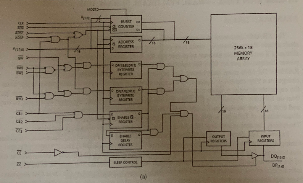
Some additional rules you need to remember for analyzing combinational logic circuits with mixed assertion levels and two or more levels of logic gates are: 1. Two bubbles in series on a signal line "cancel", just as the effects of two inverters in series do, and the term for the signal in the output expression is unchanged. If, for example, you connect the output of the first inverter in Figure 1-6a to the input of the second inverter in Figure 1-6a, the result on the final output is just A. 2. An active low signal connected to an active low input asserts that input. For example, the signal Enable# connected to the bubbled enable input of the non-inverting three-state buffer in Figure 1-6a enables the buffer when the Enable# signal is low. 3. If the active level for a signal is different from the active level of the input to which it is connected, that signal will be represented as the complement of the signal in the output expression. For example, an active high signal, B, connected to a bubbled input of a gate will appear in the output expression for the gate as B#. For another example, if an active high signal, A, is connected to an active low input such as one of the inputs on the bubbled-input OR shaped symbol in Figure 1-6b, the A term will be complemented in the output expression as shown above the signal. 12. Figure 1-17a shows the block diagram for a Synchronous RAM. Use the rules we gave you for analyzing multi-level circuits with bubbles to help you write the logic expression for the signals that assert the CLR# signal in the Burst Counter. MODES AA BURST 00 COUNTER ADDRESS REGISTER 256k x 18 MEMORY ARRAY 318 P DP15 sp) BYTEWRITE REGISTER D DPIZODPI11 BYTEWRITE REGISTER ENABLE REGISTER LSLSL 3 ENABLE DELAY REGISTER OUTPUT REGISTERS INPUT REGISTERS SLEEP CONTROL DQ11501 DP11.01 (a) Some additional rules you need to remember for analyzing combinational logic circuits with mixed assertion levels and two or more levels of logic gates are: 1. Two bubbles in series on a signal line "cancel", just as the effects of two inverters in series do, and the term for the signal in the output expression is unchanged. If, for example, you connect the output of the first inverter in Figure 1-6a to the input of the second inverter in Figure 1-6a, the result on the final output is just A. 2. An active low signal connected to an active low input asserts that input. For example, the signal Enable# connected to the bubbled enable input of the non-inverting three-state buffer in Figure 1-6a enables the buffer when the Enable# signal is low. 3. If the active level for a signal is different from the active level of the input to which it is connected, that signal will be represented as the complement of the signal in the output expression. For example, an active high signal, B, connected to a bubbled input of a gate will appear in the output expression for the gate as B#. For another example, if an active high signal, A, is connected to an active low input such as one of the inputs on the bubbled-input OR shaped symbol in Figure 1-6b, the A term will be complemented in the output expression as shown above the signal. 12. Figure 1-17a shows the block diagram for a Synchronous RAM. Use the rules we gave you for analyzing multi-level circuits with bubbles to help you write the logic expression for the signals that assert the CLR# signal in the Burst Counter. MODES AA BURST 00 COUNTER ADDRESS REGISTER 256k x 18 MEMORY ARRAY 318 P DP15 sp) BYTEWRITE REGISTER D DPIZODPI11 BYTEWRITE REGISTER ENABLE REGISTER LSLSL 3 ENABLE DELAY REGISTER OUTPUT REGISTERS INPUT REGISTERS SLEEP CONTROL DQ11501 DP11.01 (a)
Step by Step Solution
There are 3 Steps involved in it

Get step-by-step solutions from verified subject matter experts