

Question: Steel Rule Deformation Analysis P: Applied point load ( N or k g * m s 2 ) . x : Distance from the fixed
Steel Rule Deformation Analysis
P: Applied point load N or
x : Distance from the fixed end to the point of interest m or cm
L: Total length of the cantilever beam m or cm
E: Young's modulus of the material Pa or
I: Moment of inertia of the beam's crosssectional area
Where:
Youngs Modulus for steel
Moment of inertia
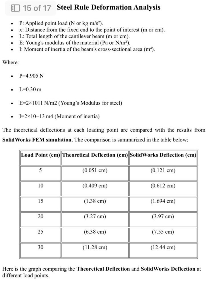
The theoretical deflections at each loading point are compared with the results from
SolidWorks FEM simulation. The comparison is summarized in the table below:
tableLoad Point cmTheoretical Deflection cmSolidWorks Deflection cm
Calculation Using above tabl:
A Calculate the deformation at various points along the beam using beam deflection formulas, such as:
delta F L E Ifor a cantilever beam, point load at end
where:
F Force applied.
L Length of the beam.
E Modulus of elasticity of the beam material.
I Moment of inertia of the beam crosssection.
B Compute the standard deviation of the measured deflections to understand experimental variability.
NOTE: IF YOU SOLVE CORRECT A&B THEN I WILL GIVE YOU GOOD REVIEW
Step by Step Solution
There are 3 Steps involved in it
1 Expert Approved Answer
Step: 1 Unlock

Question Has Been Solved by an Expert!
Get step-by-step solutions from verified subject matter experts
Step: 2 Unlock
Step: 3 Unlock