

Question: Step 1 Start from the design step. a . Read ch 8 . 2 Seven - Segment Displays of the Tarnoff textbook. b . Instead
Step
Start from the design step.
a Read ch SevenSegment Displays of the Tarnoff textbook.
b Instead of a circuit to display hexadecimal digits ~ and A~F we will build a circuit to display decimal digits ~ only.
c Truth table: we will only use the first rows of Fig from ch The last rows for hex AF become dont care conditions. Include a copy of the revised truth table in your project document. The truth table should still show rows but with dont care conditions.
d Provide a simplified Boolean expression for each of the outputs a ~ g Use whatever simplification method you like, but you must use the dont care cells and show your work with steps such as kmaps Creating kmaps on the computer is a good idea. Make sure another person not you, as you did the work can read your groupings and follow how each group is simplified.
Step
Create a circuit in Logisim piece by piece based on your simplification result from Step Only use AND, OR and NOT gates. Your circuit should have four inputs and outputs.
Label every inputoutput pin and every ANDOR gate in your circuit. Labels are like comments in a program and can help us track our work, especially when we need to correct errors. Label an AND gate with the term generated, like ABD and an OR gate with the function name, like W
Add your name, Park ID and date to your circuit using the text tool. Save your circuit as UnitYourLastNamecirc. Test your circuit to make sure it works properly before proceeding to the next step. Document your testing in the project document.
Step
Now attach a segment display to your a~g outputs. Figure shows where a segment display is listed in Logisim. Figure shows the mappings between a~g segments and the dot and the pins of the segment display component. The rightmost pin in the bottom the dot is connected to a constant as we dont need this dot. Use a Constant component Figure and change its value attribute to If needed, see the Help menu Library reference InputOutput Library segment Display.
Display
Figure
Figure
Top four pins from left to right: g f a b;
Bottom three pins from left to right: e d c
Figure
Do not delete the a~g output pins when attaching the segment display. Add additional wire before each output component as shown below. Save your circuit as UnitYourLastNamesegcirc. Test your circuit and document your testing in the project document.
Step
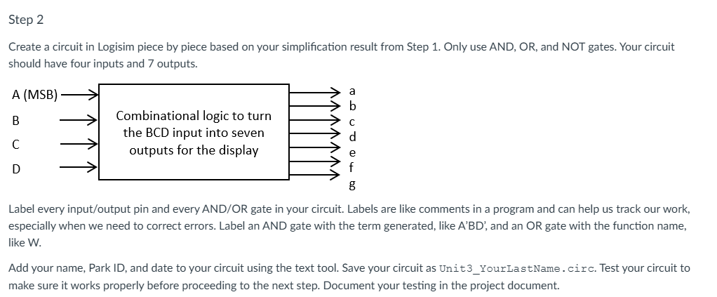
Create a circuit in Logisim piece by piece based on your simplification result from Step Only use AND, OR and NOT gates. Your circuit
should have four inputs and outputs.
Label every inputoutput pin and every ANDOR gate in your circuit. Labels are like comments in a program and can help us track our work,
especially when we need to correct errors. Label an AND gate with the term generated, like A'BD', and an OR gate with the function name,
like W
Add your name, Park ID and date to your circuit using the text tool. Save your circuit as UnitYourLastNamecirc. Test your circuit to
make sure it works properly before proceeding to the next step. Document your testing in the project document.
Display
The BCD to
decimal circuit longrightarrow.
b
Step by Step Solution
There are 3 Steps involved in it
1 Expert Approved Answer
Step: 1 Unlock

Question Has Been Solved by an Expert!
Get step-by-step solutions from verified subject matter experts
Step: 2 Unlock
Step: 3 Unlock