

Question: STEP BY STEP HOW TO CREATE THIS SPECIFIC ASSEMBLY Problem Statement: You are working as a Design Engineer in a manufacturing facility where the automation
STEP BY STEP HOW TO CREATE THIS SPECIFIC ASSEMBLY
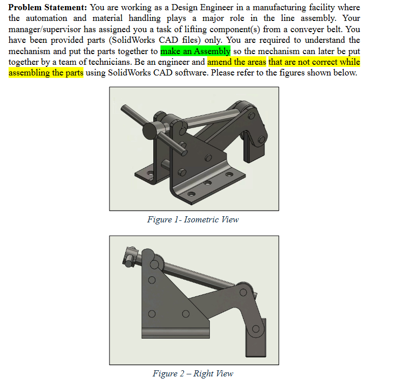
Problem Statement: You are working as a Design Engineer in a manufacturing facility where the automation and material handling plays a major role in the line assembly. Your managersupervisor has assigned you a task of lifting components from a conveyer belt. You have been provided parts SolidWorks CAD files only. You are required to understand the mechanism and put the parts together to make an Assembly so the mechanism can later be put together by a team of technicians. Be an engineer and amend the areas that are not correct while assembling the parts using SolidWorks CAD software. Please refer to the figures shown below.
Figure Isometric Vlew
SUPPORTRIGHT xx ARM x GRIP x PIN A xl HINGE A xx HINGE B x SHAFT x HANDLE x PIN B x PIN C x SUPPORT LEFT xl
Figure Exploded View
Further Considerations:
There are several pin types make sure to place them in their appropriate location see Figure
Exploded View
The right support must be fixed not floating and consequently should be the first part added
to the assembly space.
All parts other than the right support must float, with their respective positions defined using
mates.
Use a Limit mate Limit Distance or Limit Angle to control the assembly's range of motion
to match the movement demonstrated in the provided video ExtraCredit
The grip must remain vertical throughout the range of motion.
All pins must be centered with respect to the two supports.
You may not use the "Lock" mate, but you may select the option to lock rotation in a
Concentric mate to fully define a cylindrical component pin with no other useable features.
The handle must be centered with respect to the shaft.
STEP BY STEP AS IN HOW TO CREATE THIS SPECIFIC ASSEMBLY PLEASE AND THANK YOU
Step by Step Solution
There are 3 Steps involved in it
1 Expert Approved Answer
Step: 1 Unlock

Question Has Been Solved by an Expert!
Get step-by-step solutions from verified subject matter experts
Step: 2 Unlock
Step: 3 Unlock