

Water is to be transported from a collection tank at a Desalination Plant to a reservoir via
Question:
Water is to be transported from a collection tank at a Desalination Plant to a reservoir via the pipework system shown below. The pump station is to incorporate four TKL 250 x 300 – 500A ST pumps, arranged in parallel as shown below. The pumps operate in a duty-standby arrangement, with 3 pumps operating to achieve the design peak flow rate of 600 l/s (while the other pump sits idle).
(a) Calculate the system curve, plot it on the blank chart provided. Detach the chart and submit it with your assignment. Calculating a minimum of 3 points covering the full chart range will suffice, though you may calculate more if you choose. You may assume that flow is evenly divided between the three duty pumps, and that straight pipe losses in the parallel pipework section are negligible (but fitting losses in the parallel pipework section may not be neglected). The mains pipework diameter is 600 mm, and the parallel pipework diameter is 300 mm.
(b) Determine the overall duty point for the three pumps operating in parallel to deliver 600 l/s, the individual duty point for each pump, the efficiency at which each pump operates and the required impeller diameter.
(c) system redesign is proposed where 2 more TKL 250 x 300 – 500A ST pumps would be added to enable 5 duty pumps to deliver 1000 l/s. State (with reasons) whether this is feasible, and, if it is not, what modifications you would need to make to the system to render it feasible.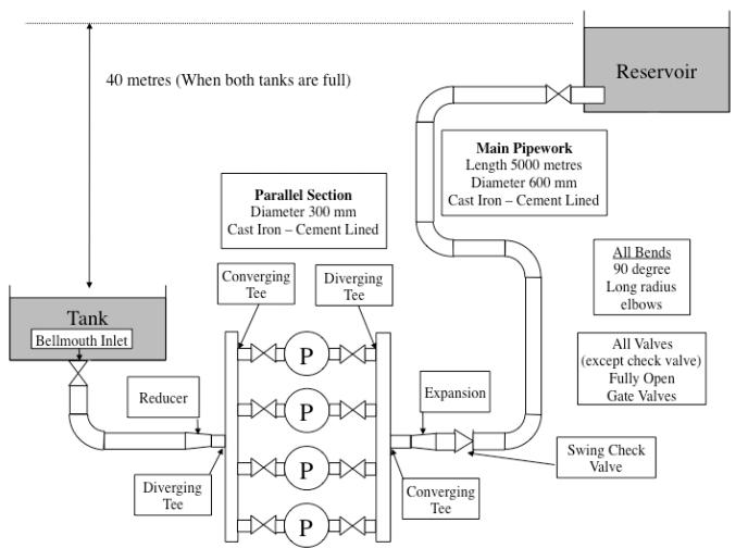
Expert Answer:


Accounting
ISBN: 978-0324662962
23rd Edition
Authors: Jonathan E. Duchac, James M. Reeve, Carl S. Warren
