

Question: table [ [ , 1 . Draw the network with all the data as provided. ] , [ , 2 . Run a load
table Draw the network with all the data as provided. Run a load flow to determine your steady state conditions.Steps:table Perform short circuit analysis at different buses. Select and size all CTtable Connect relays where appropriate. Carry out coordinating studies to adjust relay settings. Check for relay operation for selected fault locations.Report:Prepare a detailed report of your work.Team Work:,You may work in a group of two but no more.tableReportSubmission:Tuesday, December class time sharp.
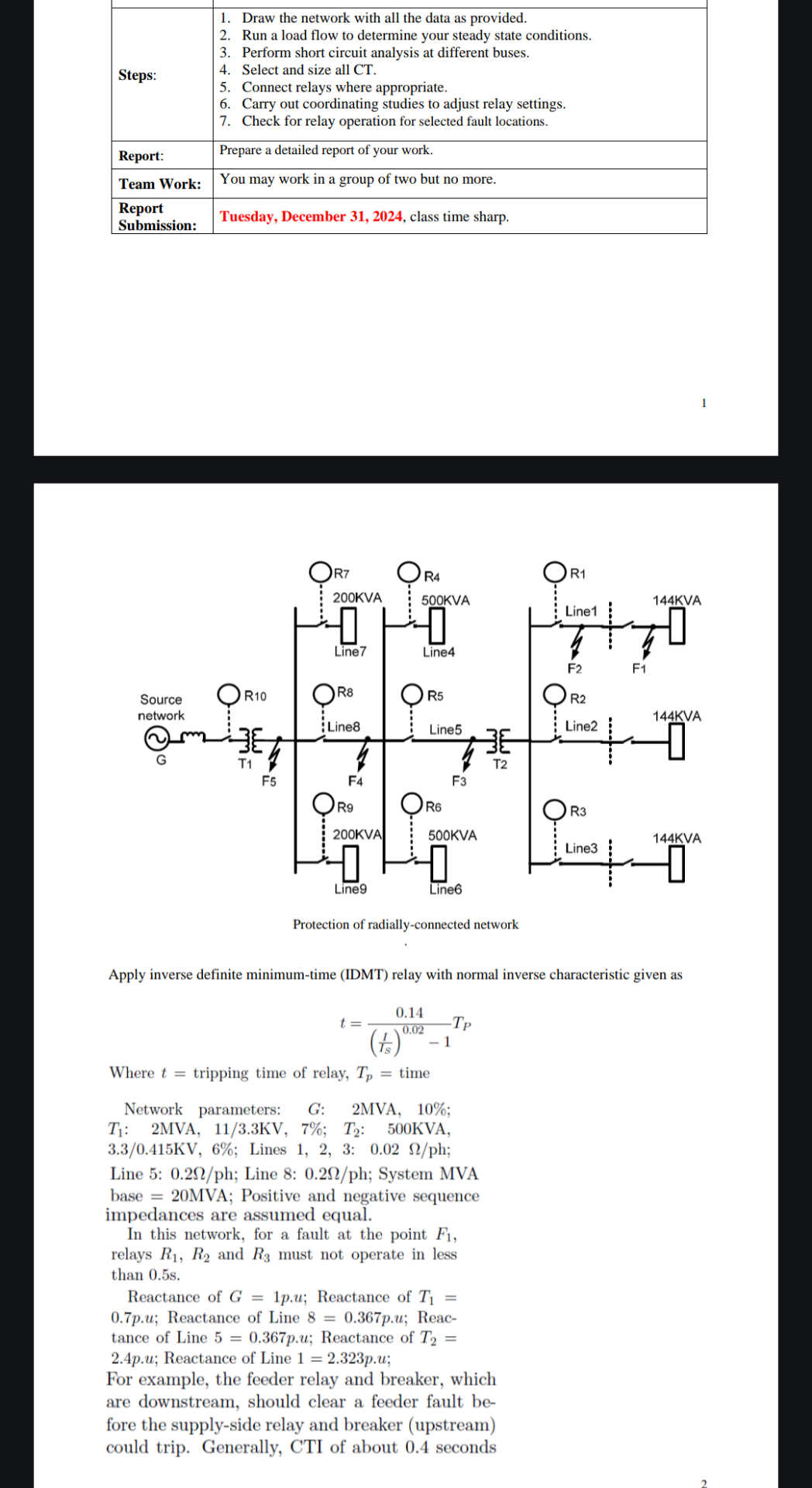
Apply inverse definite minimumtime IDMT relay with normal inverse characteristic given as
Where tripping time of relay, time
Network parameters: G: MVA, ;
:MVA,;:KVA,
KV; Lines : ;
Line : ; Line : ; System MVA
base MVA; Positive and negative sequence impedances are assumed equal.
In this network, for a fault at the point relays and must not operate in less than s
Reactance of ; Reactance of puReactance of Line pu; Reactance of Line pu; Reactance of pu; Reactance of Line pu;
For example, the feeder relay and breaker, which are downstream, should clear a feeder fault before the supplyside relay and breaker upstream could trip. Generally, CTI of about seconds
solve this question on paper, correct solution to give like
Step by Step Solution
There are 3 Steps involved in it
1 Expert Approved Answer
Step: 1 Unlock

Question Has Been Solved by an Expert!
Get step-by-step solutions from verified subject matter experts
Step: 2 Unlock
Step: 3 Unlock