

Question: Table 1 The key given in Table 1 is executed on the PIC microcontroller in the circuit according to the code fragment given at the
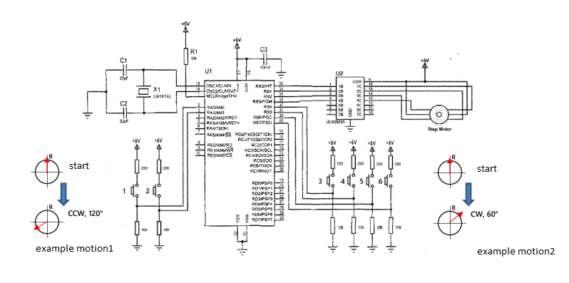
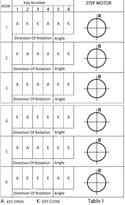
Table 1
The key given in Table 1 is executed on the PIC microcontroller in the circuit according to the code fragment given at the bottom
what happens to the direction and angle of motion of the stepper motor rotor (relative to the given reference position (R)) when their position is applied?
(show by calculating). Results given without an account will not be evaluated.
5 the 5V stepper motor used in the circuit has a step angle of 1.5. Each key combination given in Table 1
it is not applied until the engine reaches its final position (stops). The engine will start from point R (Row 1).
#include
#fuses XT,NOWDT,NOPROTECT,NOBROWNOUT
#use delay(clock=4000000) // four millions
#use fast_io(a)
#use fast_io(b)
int i,j,x=5,y=0;
int seri[]={10,9,11,8,7,12,14,4,13,6,5,2,15,3,0,1};
#int_rb
void of_1()
{ if(input(pin_b4)) x = x + 2;
if(input(pin_b5)) x = x * 2;
if(input(pin_b6)) x = x - 4;
if(input(pin_b7)) x = x * 3;
if(input(pin_a0)) x = x * 2;
if(input(pin_a1)) y = 1;
for(i=0;i { if(y==0) for(j=0;j { output_b(series[j]); delay_ms(50); } else for(j=15;j>=0;j-2) { output_b(series[j]); delay_ms(50); } } x = 10; y = 0; } void main () set_tris_a(0x0F); set_tris_b(0xF0); output_b(0x00); enable_interrupts(int_rb); enable_interrupts(GLOBAL); while(1); { // Assume required setups;
Step by Step Solution
There are 3 Steps involved in it

Get step-by-step solutions from verified subject matter experts