

Question: Table 5 . 1 Typical values of resistivity for different soils. Table 5 . 2 . Earthing resistance and the soil resistivity Self - Evaluation
Table Typical values of resistivity for different soils.
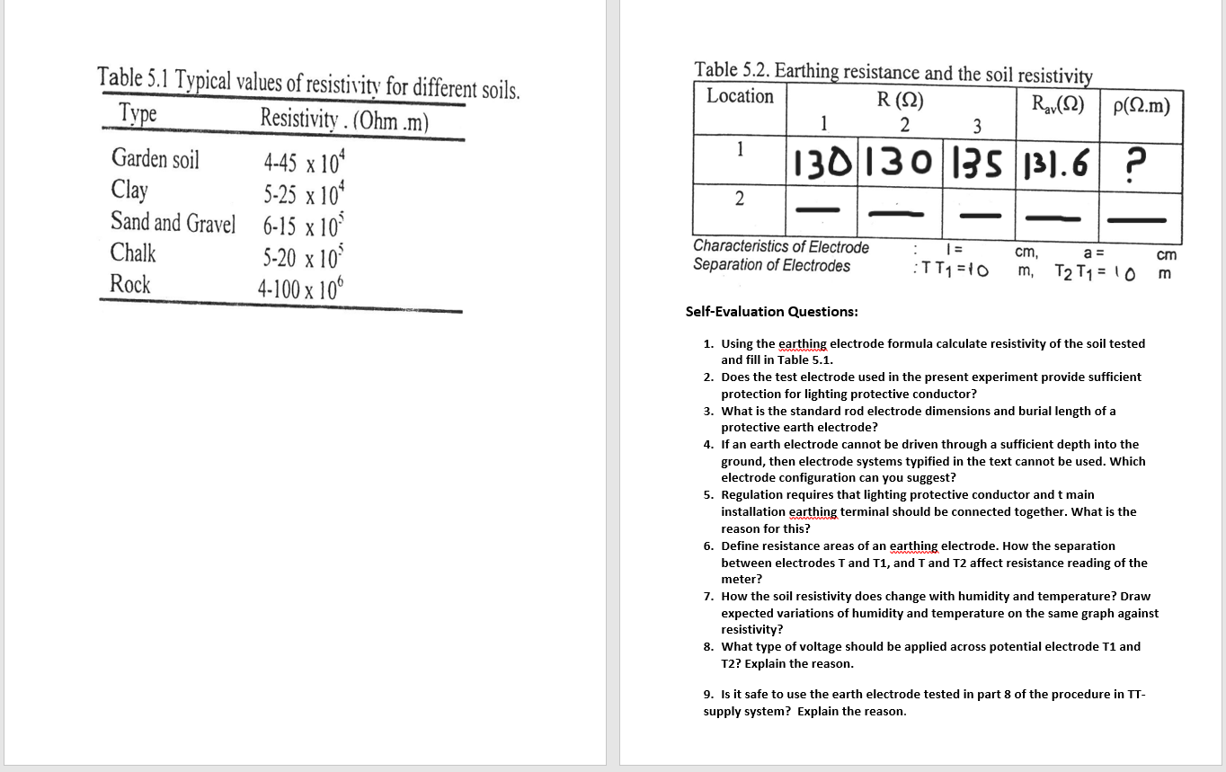
Table Earthing resistance and the soil resistivity
SelfEvaluation Questions:
Using the earthing electrode formula calculate resistivity of the soil tested and fill in Table
Does the test electrode used in the present experiment provide sufficient protection for lighting protective conductor?
What is the standard rod electrode dimensions and burial length of a protective earth electrode?
If an earth electrode cannot be driven through a sufficient depth into the ground, then electrode systems typified in the text cannot be used. Which electrode configuration can you suggest?
Regulation requires that lighting protective conductor and t main installation earthing terminal should be connected together. What is the reason for this?
Define resistance areas of an earthing electrode. How the separation between electrodes T and T and T and T affect resistance reading of the meter?
How the soil resistivity does change with humidity and temperature? Draw expected variations of humidity and temperature on the same graph against resistivity?
What type of voltage should be applied across potential electrode T and T Explain the reason.
Is it safe to use the earth electrode tested in part of the procedure in TTsupply system? Explain the reason.
Step by Step Solution
There are 3 Steps involved in it
1 Expert Approved Answer
Step: 1 Unlock

Question Has Been Solved by an Expert!
Get step-by-step solutions from verified subject matter experts
Step: 2 Unlock
Step: 3 Unlock