

Question: TABLE 7: Turbine geometry and setup values for prototype and model. Parameters Symbol Unit Prototypes values Q Lts/s 140 Flow rate Head PCD Selected model
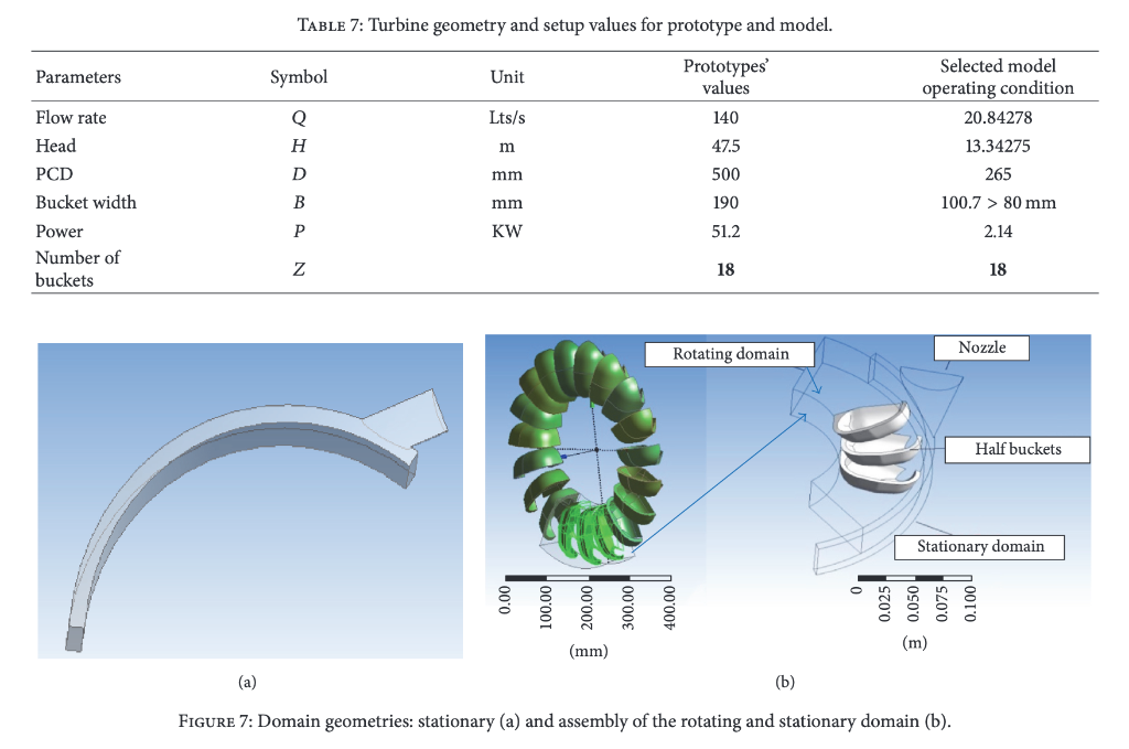
TABLE 7: Turbine geometry and setup values for prototype and model. Parameters Symbol Unit Prototypes values Q Lts/s 140 Flow rate Head PCD Selected model operating condition 20.84278 13.34275 265 H m 47.5 500 D mm B mm 190 100.7 > 80 mm P KW 51.2 2.14 Bucket width Power Number of buckets Z 18 18 Nozzle Rotating domain Half buckets Stationary domain . 0.00 100.00 200.00 300.00 400.000 0.025 Moso'o 0.075 0.100 U (mm) (a) (b) FIGURE 7: Domain geometries: stationary (a) and assembly of the rotating and stationary domain (b). Q4. You are involved in a project to improve the design of a Pelton turbine and have commissioned some computational fluid dynamics (CFD) simulations of performance for different bucket geometries. To keep the cost of the CFD to a reasonable level, the simulations are done for three buckets only, as in the research paper included with this assignment (see figures 7 ff). A prototype turbine is to be built to the most efficient design. What is your judgement on the accuracy of the CFD predictions of turbine efficiency? What other simulations could be done to obtain further information? If you suspect that frictional losses (windage, bearing friction etc) are important how would you use the prototype to determine their magnitude
Step by Step Solution
There are 3 Steps involved in it

Get step-by-step solutions from verified subject matter experts