Question: Table 9-1. Maximum Water-Cementitious Material Ratios and Minimum Design Strengths for Various Exposure Conditions Maximum water-cementitious material Minimum design compressive strength, Exposure condition ratio by
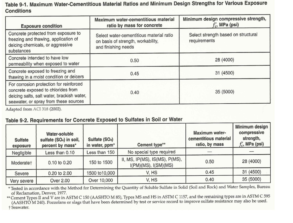
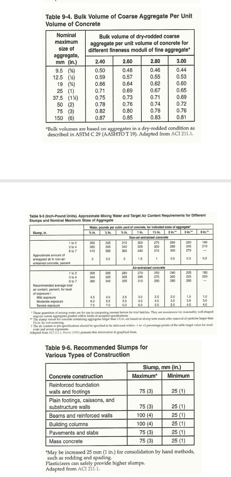
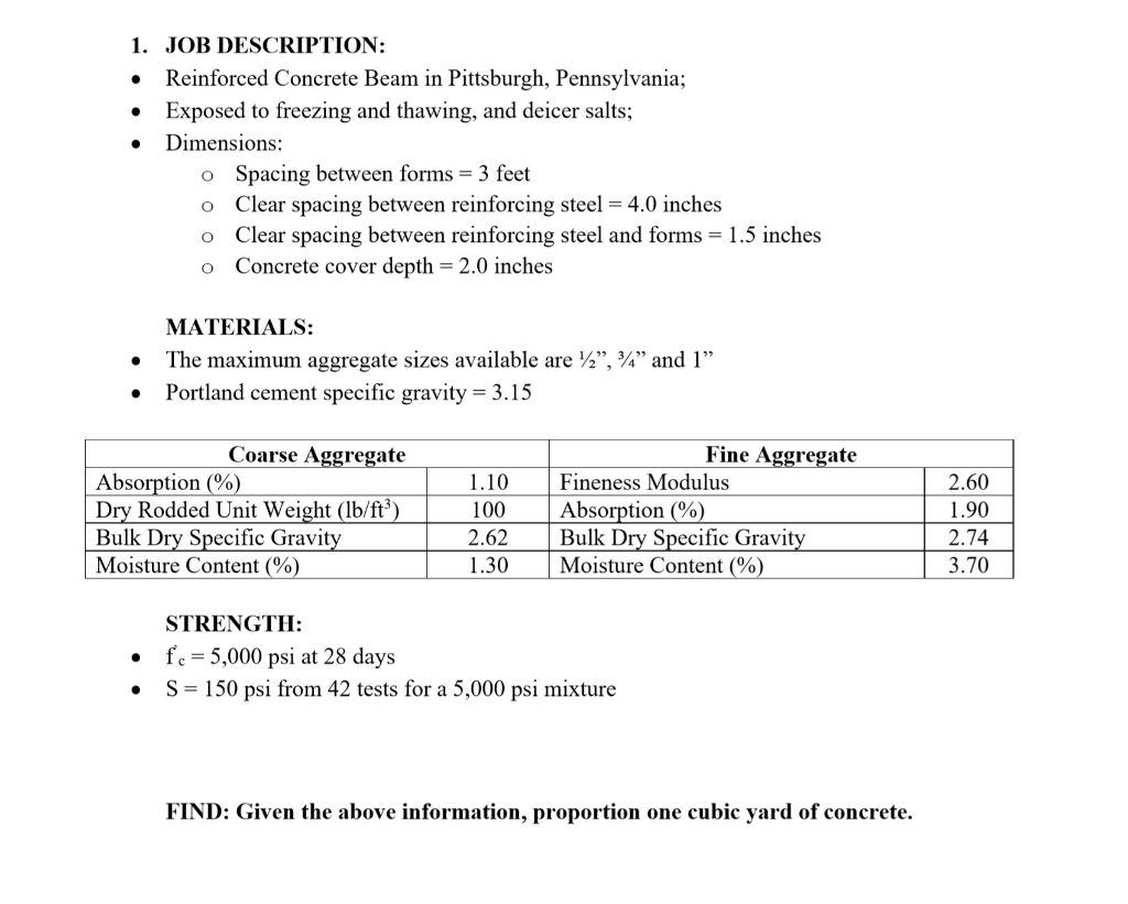
Table 9-1. Maximum Water-Cementitious Material Ratios and Minimum Design Strengths for Various Exposure Conditions Maximum water-cementitious material Minimum design compressive strength, Exposure condition ratio by mass for concrete f, MPa (psi) Concrete protected from exposure to Select water-cementitious material ratio Select strength based on structural freezing and thawing, application of on basis of strength, workability, requirements deicing chemicals, or aggressive and finishing needs substances Concrete intended to have low 0.50 28 (4000) permeability when exposed to water Concrete exposed to freezing and 0.45 31 (4500) thawing in a moist condition or deicers For corrosion protection for reinforced concrete exposed to chlorides from 0.40 35 (5000) deicing salts, salt water, brackish water, seawater, or spray from these sources Adapted from ACI 318 (2002). Table 9-2. Requirements for Concrete Exposed to Sulfates in Soil or Water Minimum design Water-soluble Maximum water compressive Sulfate sulfate (SO4) in soil, Sulfate (S04) cementitious material strength, exposure percent by mass in water, ppm* Cement type** ratio, by mass f, MPa (psi) Negligible Less than 0.10 Less than 150 No special type required II, MS, IP(MS), IS(MS), P(MS), Moderatet 0.10 to 0.20 150 to 1500 0.50 28 (4000) (PM)(MS), (SM)(MS) Severe 0.20 to 2.00 1500 to 10,000 V, HS 0.45 31 (4500) Very severe Over 2.00 Over 10,000 V, HS 0.40 35 (5000) * Tested in accordance with the Method for Determining the Quantity of Soluble Sulfate in Solid (Soil and Rock) and Water Samples, Bureau of Reclamation, Denver, 1977. **Cement Types II and V are in ASTM C 150 (AASHTO M 85), Types MS and HS in ASTM C 1157, and the remaining types are in ASTM C 595 (AASHTO M 240). Pozzolans or slags that have been determined by test or service record to improve sulfate resistance may also be used. + Seawater. Table 9-4. Bulk Volume of Coarse Aggregate Per Unit Volume of Concrete Bulk volume of dry-rodded coarse aggregate per unit volume of concrete for different fineness moduli of fine aggregate* 2.40 2.60 0.48 Nominal maximum size of aggregate, mm (in.) 9.5 (4) 12.5 (12) 19 (24) 25 (1) 37.5 (112) 50 (2) 75 (3) 150 (6) 0.57 0.50 0.59 0.66 0.71 0.75 0.78 0.82 0.87 0.64 0.69 0.73 0.76 0.80 0.85 2.80 0.46 0.55 0.62 0.67 0.71 0.74 0.78 0.83 3.00 0.44 0.53 0.60 0.65 0.69 0.72 0.76 0.81 *Bulk volumes are based on aggregates in a dry-rodded condition as described in ASTM C 29 (AASHTOT 19). Adapted from ACI 211.1. 6 in. Table 9-5 (Inch-Pound Units). Approximate Mixing Water and Target Air Content Requirements for Different Slumps and Nominal Maximum Sizes of Aggregate Water, pounds per cubic yard of concrete, for indicated sizes of aggregate Slump, in % in. in. % in. 1 in 1% in. 2 in. 3 in. Non-air-entrained concrete 1 to 2 350 335 315 300 275 260 220 190 3 to 4 385 365 340 325 300 285 245 210 6 to 7 410 385 360 340 315 300 270 Approximate amount of entrapped air in non-air- 3 2.5 2 1.5 1 0.5 0.3 0.2 entrained concrete, percent Air-entrained concrete 1 to 2 305 295 280 270 250 240 205 180 3 to 4 340 325 305 295 275 265 225 200 6 to 7 365 345 325 310 290 280 260 Recommended average total air content, percent, for level of exposure: Mild exposure 4.5 4.0 3.5 3.0 25 2.0 1.5 1.0 Moderate exposure 6.0 5.5 5.0 4.5 4.5 3.5 3.5 3.0 Severe exposure 7.5 7.0 6.0 6.0 5.5 5.0 4.5 4.0 These quantities of mixing water are for use in computing cement factors for trial batches. They are macimums for reasonably well-shaped angular coarse aggregates graded within limits of accepted specifications, ** The slump values for concrete containing aggregates larger than 1% in are based on slump tests made after removal of particles larger than 1% in by wet screening The air content in job specifications should be specified to be delivered within 1 to +2 percentage points the table target value for mod. erate and d severe exposures Adapted from ACI 211.1. Hover (1995) presents this information graphical form Table 9-6. Recommended Slumps for Various Types of Construction Slump, mm (in.) Maximum* Minimum 75 (3) 25 (1) Concrete construction Reinforced foundation walls and footings Plain footings, caissons, and substructure walls Beams and reinforced walls Building columns Pavements and slabs Mass concrete 75 (3) 100 (4) 100 (4) 75 (3) 75 (3) 25 (1) 25 (1) 25 (1) 25 (1) 25 (1) *May be increased 25 mm (1 in.) for consolidation by hand methods, such as rodding and spading. Plasticizers can safely provide higher slumps. Adapted from ACI 211.1. . . . 1. JOB DESCRIPTION: Reinforced Concrete Beam in Pittsburgh, Pennsylvania; Exposed to freezing and thawing, and deicer salts; Dimensions: o Spacing between forms = 3 feet Clear spacing between reinforcing steel = 4.0 inches Clear spacing between reinforcing steel and forms = 1.5 inches Concrete cover depth = 2.0 inches O O O . MATERIALS: The maximum aggregate sizes available are 1/2, 24 and 1 Portland cement specific gravity = 3.15 Coarse Aggregate Absorption (%) Dry dded Unit Weight (lb/ft) Bulk Dry Specific Gravity Moisture Content (%) 1.10 100 2.62 1.30 Fine Aggregate Fineness Modulus Absorption (%) Bulk Dry Specific Gravity Moisture Content (%) 2.60 1.9 2.74 3.70 . STRENGTH: fc = 5,000 psi at 28 days S= 150 psi from 42 tests for a 5,000 psi mixture FIND: Given the above information, proportion one cubic yard of concrete. Table 9-1. Maximum Water-Cementitious Material Ratios and Minimum Design Strengths for Various Exposure Conditions Maximum water-cementitious material Minimum design compressive strength, Exposure condition ratio by mass for concrete f, MPa (psi) Concrete protected from exposure to Select water-cementitious material ratio Select strength based on structural freezing and thawing, application of on basis of strength, workability, requirements deicing chemicals, or aggressive and finishing needs substances Concrete intended to have low 0.50 28 (4000) permeability when exposed to water Concrete exposed to freezing and 0.45 31 (4500) thawing in a moist condition or deicers For corrosion protection for reinforced concrete exposed to chlorides from 0.40 35 (5000) deicing salts, salt water, brackish water, seawater, or spray from these sources Adapted from ACI 318 (2002). Table 9-2. Requirements for Concrete Exposed to Sulfates in Soil or Water Minimum design Water-soluble Maximum water compressive Sulfate sulfate (SO4) in soil, Sulfate (S04) cementitious material strength, exposure percent by mass in water, ppm* Cement type** ratio, by mass f, MPa (psi) Negligible Less than 0.10 Less than 150 No special type required II, MS, IP(MS), IS(MS), P(MS), Moderatet 0.10 to 0.20 150 to 1500 0.50 28 (4000) (PM)(MS), (SM)(MS) Severe 0.20 to 2.00 1500 to 10,000 V, HS 0.45 31 (4500) Very severe Over 2.00 Over 10,000 V, HS 0.40 35 (5000) * Tested in accordance with the Method for Determining the Quantity of Soluble Sulfate in Solid (Soil and Rock) and Water Samples, Bureau of Reclamation, Denver, 1977. **Cement Types II and V are in ASTM C 150 (AASHTO M 85), Types MS and HS in ASTM C 1157, and the remaining types are in ASTM C 595 (AASHTO M 240). Pozzolans or slags that have been determined by test or service record to improve sulfate resistance may also be used. + Seawater. Table 9-4. Bulk Volume of Coarse Aggregate Per Unit Volume of Concrete Bulk volume of dry-rodded coarse aggregate per unit volume of concrete for different fineness moduli of fine aggregate* 2.40 2.60 0.48 Nominal maximum size of aggregate, mm (in.) 9.5 (4) 12.5 (12) 19 (24) 25 (1) 37.5 (112) 50 (2) 75 (3) 150 (6) 0.57 0.50 0.59 0.66 0.71 0.75 0.78 0.82 0.87 0.64 0.69 0.73 0.76 0.80 0.85 2.80 0.46 0.55 0.62 0.67 0.71 0.74 0.78 0.83 3.00 0.44 0.53 0.60 0.65 0.69 0.72 0.76 0.81 *Bulk volumes are based on aggregates in a dry-rodded condition as described in ASTM C 29 (AASHTOT 19). Adapted from ACI 211.1. 6 in. Table 9-5 (Inch-Pound Units). Approximate Mixing Water and Target Air Content Requirements for Different Slumps and Nominal Maximum Sizes of Aggregate Water, pounds per cubic yard of concrete, for indicated sizes of aggregate Slump, in % in. in. % in. 1 in 1% in. 2 in. 3 in. Non-air-entrained concrete 1 to 2 350 335 315 300 275 260 220 190 3 to 4 385 365 340 325 300 285 245 210 6 to 7 410 385 360 340 315 300 270 Approximate amount of entrapped air in non-air- 3 2.5 2 1.5 1 0.5 0.3 0.2 entrained concrete, percent Air-entrained concrete 1 to 2 305 295 280 270 250 240 205 180 3 to 4 340 325 305 295 275 265 225 200 6 to 7 365 345 325 310 290 280 260 Recommended average total air content, percent, for level of exposure: Mild exposure 4.5 4.0 3.5 3.0 25 2.0 1.5 1.0 Moderate exposure 6.0 5.5 5.0 4.5 4.5 3.5 3.5 3.0 Severe exposure 7.5 7.0 6.0 6.0 5.5 5.0 4.5 4.0 These quantities of mixing water are for use in computing cement factors for trial batches. They are macimums for reasonably well-shaped angular coarse aggregates graded within limits of accepted specifications, ** The slump values for concrete containing aggregates larger than 1% in are based on slump tests made after removal of particles larger than 1% in by wet screening The air content in job specifications should be specified to be delivered within 1 to +2 percentage points the table target value for mod. erate and d severe exposures Adapted from ACI 211.1. Hover (1995) presents this information graphical form Table 9-6. Recommended Slumps for Various Types of Construction Slump, mm (in.) Maximum* Minimum 75 (3) 25 (1) Concrete construction Reinforced foundation walls and footings Plain footings, caissons, and substructure walls Beams and reinforced walls Building columns Pavements and slabs Mass concrete 75 (3) 100 (4) 100 (4) 75 (3) 75 (3) 25 (1) 25 (1) 25 (1) 25 (1) 25 (1) *May be increased 25 mm (1 in.) for consolidation by hand methods, such as rodding and spading. Plasticizers can safely provide higher slumps. Adapted from ACI 211.1. . . . 1. JOB DESCRIPTION: Reinforced Concrete Beam in Pittsburgh, Pennsylvania; Exposed to freezing and thawing, and deicer salts; Dimensions: o Spacing between forms = 3 feet Clear spacing between reinforcing steel = 4.0 inches Clear spacing between reinforcing steel and forms = 1.5 inches Concrete cover depth = 2.0 inches O O O . MATERIALS: The maximum aggregate sizes available are 1/2, 24 and 1 Portland cement specific gravity = 3.15 Coarse Aggregate Absorption (%) Dry dded Unit Weight (lb/ft) Bulk Dry Specific Gravity Moisture Content (%) 1.10 100 2.62 1.30 Fine Aggregate Fineness Modulus Absorption (%) Bulk Dry Specific Gravity Moisture Content (%) 2.60 1.9 2.74 3.70 . STRENGTH: fc = 5,000 psi at 28 days S= 150 psi from 42 tests for a 5,000 psi mixture FIND: Given the above information, proportion one cubic yard of concrete


