

Question: TABLE P 6 - 2 Data for Problems 6 - 6 to 6 - 7 ( ddagger ) Drawings of these linkages
TABLE P Data for Problems to
ddagger Drawings of these linkages are in the PDF Problem Workbook folder on the DVD
FIGURE P
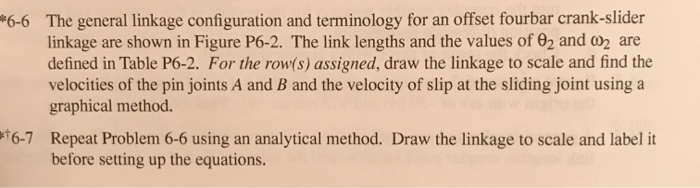
Configuration and terminology for Problems The general linkage configuration and terminology for an offset fourbar crankslider linkage are shown in Figure P The link lengths and the values of theta and omega are defined in Table P For the rows assigned, draw the linkage to scale and find the velocities of the pin joints A and B and the velocity of slip at the sliding joint using a graphical method.
Repeat Problem using an analytical method. Draw the linkage to scale and label it before setting up the equations.
Step by Step Solution
There are 3 Steps involved in it
1 Expert Approved Answer
Step: 1 Unlock

Question Has Been Solved by an Expert!
Get step-by-step solutions from verified subject matter experts
Step: 2 Unlock
Step: 3 Unlock