

Question: Task 1: Pedestrian Stoplight Many crosswalks have a stoplight that tells pedestrians when they can cross the street. They use three phases: 1. Go
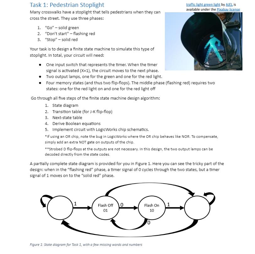
Task 1: Pedestrian Stoplight Many crosswalks have a stoplight that tells pedestrians when they can cross the street. They use three phases: 1. "Go" - solid green 2. "Don't start" - flashing red 3. "Stop" - solid red Your task is to design a finite state machine to simulate this type of stoplight. In total, your circuit will need: One input switch that represents the timer. When the timer signal is activated (X=1), the circuit moves to the next phase. Two output lamps, one for the green and one for the red light. traffic light green light by AJEL is available under the Pixabay license Four memory states (and thus two flip-flops). The middle phase (flashing red) requires two states: one for the red light on and one for the red light off Go through all five steps of the finite state machine design algorithm: 1. State diagram 2. Transition table (for J-K flip-flop) 3. Next-state table 4. Derive Boolean equations 5. Implement circuit with LogicWorks chip schematics. *If using an OR chip, note the bug in Logic Works where the OR chip behaves like NOR. To compensate, simply add an extra NOT gate on outputs of the chip. **Strobed D flip-flops at the outputs are not necessary. In this design, the two output lamps can be decoded directly from the state codes. A partially complete state diagram is provided for you in Figure 1. Here you can see the tricky part of the design: when in the "flashing red" phase, a timer signal of 0 cycles through the two states, but a timer signal of 1 moves on to the "solid red" phase. Flash Off O 01 Flash On 1 10 Figure 1: State diagram for Task 1, with a few missing words and numbers
Step by Step Solution
There are 3 Steps involved in it
To design the finite state machine for the pedestrian stoplight lets break down the steps Step 1 Sta... View full answer

Get step-by-step solutions from verified subject matter experts