

Question: Task 2 An oil hydraulics system is presented in figure 1 . Figure 2 is a schematic drawing of the same oil hydraulic system. The
Task
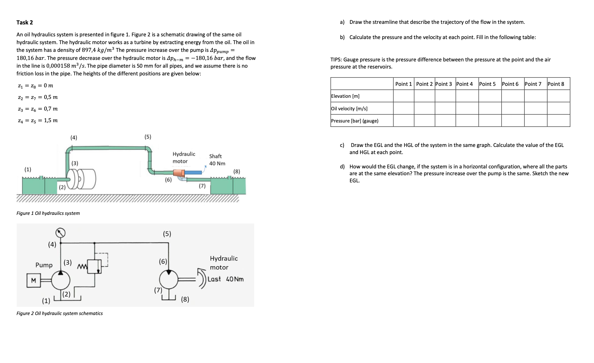
An oil hydraulics system is presented in figure Figure is a schematic drawing of the same oil
hydraulic system. The hydraulic motor works as a turbine by extracting energy from the oil. The oil in
the system has a density of The pressure increase over the pump is
The pressure decrease over the hydraulic motor is and the flow
in the line is The pipe diameter is for all pipes, and we assume there is no
friction loss in the pipe. The heights of the different positions are given below:
a Draw the streamline that describe the trajectory of the flow in the system.
b Calculate the pressure and the velocity at each point. Fill in the following table:
TIPS: Gauge pressure is the pressure difference between the pressure at the point and the air
pressure at the reservoirs.
c Draw the EGL and the HGL of the system in the same graph. Calculate the value of the EGL
and at each point.
d How would the EGL change, if the system is in a horizontal configuration, where all the parts
are at the same elevation? The pressure increase over the pump is the same. Sketch the new
EGL.
Step by Step Solution
There are 3 Steps involved in it
1 Expert Approved Answer
Step: 1 Unlock

Question Has Been Solved by an Expert!
Get step-by-step solutions from verified subject matter experts
Step: 2 Unlock
Step: 3 Unlock