

Question: Technical Objective: A state machine is sequential circuit that stores the status of something at a given time and can operate on inputs to change
Technical Objective:
A state machine is sequential circuit that stores the status of something at a given time and can operate on inputs to change the status andor cause an action or output to take place for any given change. In this lab, the design, coding and troubleshooting of a finite state machine will be investigated. To test the theory of designing with a state machine, a circuit to control the operations of a vending machine will be implemented.
Prelab :
Design a Vending machine controller that dispenses Red Bull drinks for $ The specifications are as follows.
The machine accepts dimes, nickels and quarters only. Only one coin can be input at a time.
If the dispense button is pushed before there has been $ input, it is ignored. If the button is pushed after $ has been deposited, the machine outputs the drink and any change, if applicable.
Once the total money in the machine reaches $ or more, any further deposits are immediately returned to the user.
If the coinreturn input is pressed at any time, all money is returned.
Two seven segment displays will always display the current balance in the machine.
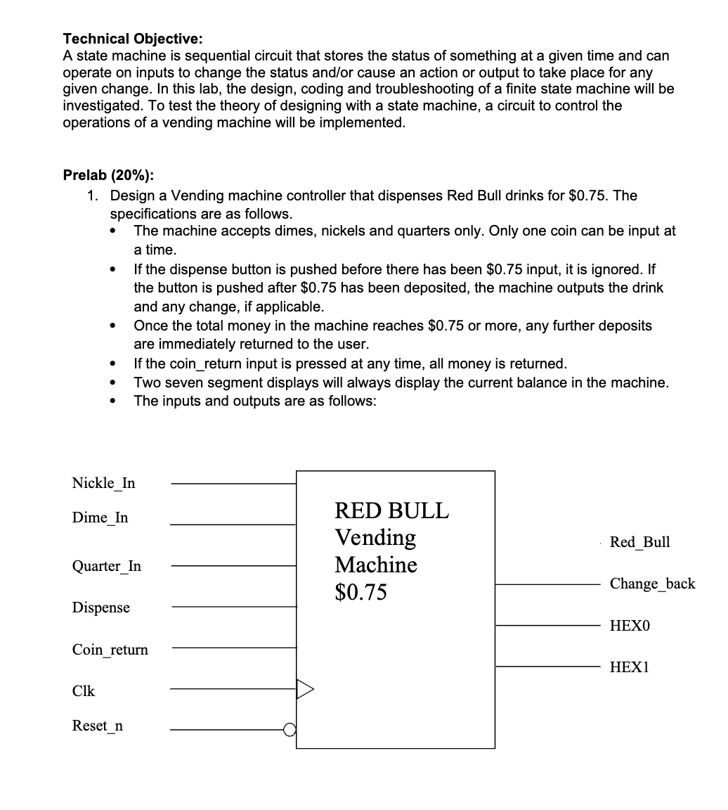
The inputs and outputs are as follows: Dime In Nickel in Quarterin: these indicate that money is being deposited. These should be connected to three slider switches on the DE board.
Coin return: This input indicates that the user would like their money back. Connect it to a slider switch.
Dispense: This input indicates that the user would like their drink. This should also be connected to a slider switch.
Clk: Since the MHz clock on the DEO board is much too fast for this application, there are two choices.
Connect clock to a pushbutton and manually clock the state machine
Create a much slower clock in the design and clock the state machine at a sim mathrmsec rate.
Resetn: this is the system reset and should be connected to Key
Change back: this output indicates that change is being returned. It should be a red LED.
Red Bull: This output indicates that the drink has been dispensed. It should be a red LED.
HEX and HEX: These are two seven segment displays. They display the amount of money in the machine.
Design Suggestions
o Make an individual process for each output. Do not assign the outputs in your nextstate logic process. The outputs must be a function of the state.
You will need a separate process to keep track of the current money in the machine. This should be a clocked process since there is memory involved. Do not put this in the nextstate logic process either. Changes to the money variable are determined by the state as indicated in the table. Write the VHDL for your vending machine controller. Synthesize the design and correct any errors or warnings. Do not ignore latch warnings. Open the state machine in the netlist viewer and verify that the state transition diagram matches your original.
Submit the following to the dropbox prior to your lab section:
a The VHDL code
b The state transition diagram generated in the netlist viewer. To generate the state transition diagram, choose Tools Netlist Viewers State Machine Viewer
Step by Step Solution
There are 3 Steps involved in it
1 Expert Approved Answer
Step: 1 Unlock

Question Has Been Solved by an Expert!
Get step-by-step solutions from verified subject matter experts
Step: 2 Unlock
Step: 3 Unlock