

Question: The 2 - in - diameter solid steel shaft shown below is simply supported at the ends. Two pulleys are keyed to the The 2
The indiameter solid steel shaft shown below is simply supported at the ends. Two pulleys are keyed to the The indiameter solid steel shaft shown below is simply supported at the ends. Two pulleys are keyed to the
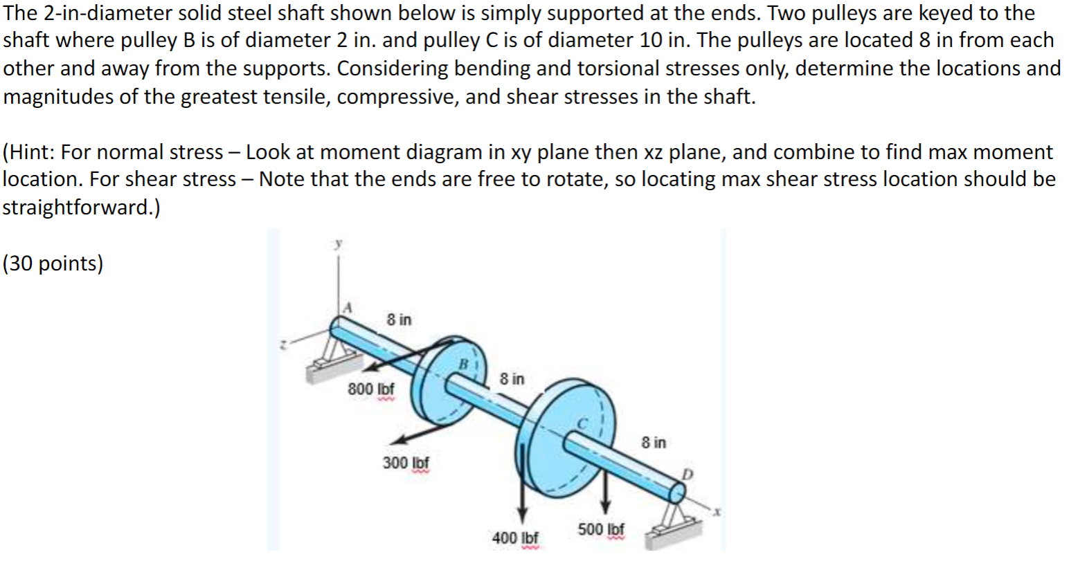
shaft where pulley is of diameter in and pulley is of diameter in The pulleys are located in from each
other and away from the supports. Considering bending and torsional stresses only, determine the locations and
magnitudes of the greatest tensile, compressive, and shear stresses in the shaft.
Hint: For normal stress Look at moment diagram in xy plane then xz plane, and combine to find max moment
location. For shear stress Note that the ends are free to rotate, so locating max shear stress location should be
straightforward.
points
shaft where pulley B is of diameter in and pulley C is of diameter in The pulleys are located in from each
other and away from the supports. Considering bending and torsional stresses only, determine the locations and
magnitudes of the greatest tensile, compressive, and shear stresses in the shaft
Step by Step Solution
There are 3 Steps involved in it
1 Expert Approved Answer
Step: 1 Unlock

Question Has Been Solved by an Expert!
Get step-by-step solutions from verified subject matter experts
Step: 2 Unlock
Step: 3 Unlock