

Question: The ball and beam control system can be divided into two separate control loops, an inner loop and an outer loop. The inner loop is
The ball and beam control system can be divided into two separate control loops, an inner loop
and an outer loop. The inner loop is used to control the angular displacement theta s of the SRV
servomechanism. Since the SRV is much faster than the ball and beam system, a separate
compensator can be used to control its response. The inner loop can be satisfactorily controlled
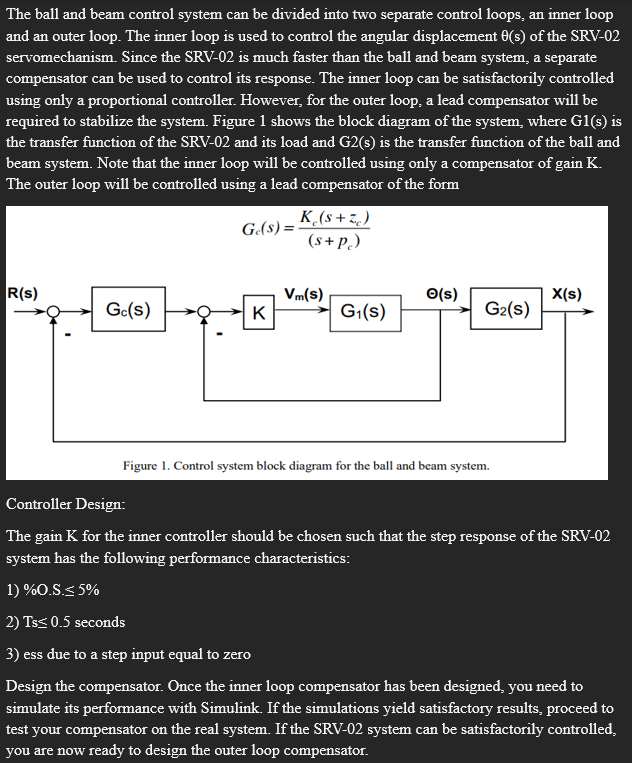
using only a proportional controller. However, for the outer loop, a lead compensator will be
required to stabilize the system. Figure shows the block diagram of the system, where Gs is
the transfer function of the SRV and its load and Gs is the transfer function of the ball and
beam system. Note that the inner loop will be controlled using only a compensator of gain K
The outer loop will be controlled using a lead compensator of the form Ge s
Figure Control system block diagram for the ball and beam system.
Controller Design:
The gain K for the inner controller should be chosen such that the step response of the SRV
system has the following performance characteristics:
OS
Ts seconds
ess due to a step input equal to zero
Design the compensator. Once the inner loop compensator has been designed, you need to
simulate its performance with Simulink. If the simulations yield satisfactory results, proceed to
test your compensator on the real system. If the SRV system can be satisfactorily controlled,
you are now ready to design the outer loop compensator.
The outer loop compensator Gcs is designed such that the ball position due to a step input is characterized by the following performance specifications:
OS
Ts seconds
ess due to a step input equal to zero
Like you did for the inner loop, use Simulink to simulate the ball position response when a step input is applied. If the simulations provide satisfactory results, proceed to test your compensator in the real system. Now, if the real system responds according to the required performance characteristics, you have finished. If the system does not respond as expected, you will have to verify your previous work plant modeling, controller design, etc. and test the modified compensators until you are successful.
Finally, give out the following:
A block diagram of the entire control system. Identify all signals and systems, including the transfer functions of both compensators.
A plot showing the step response of the system. Show the input and response signals on the same plot. Indicate the settling time, percent overshoot and steadystate error. Do this for both the inner loop alone and for the entire system.
Explain any observed differences between the simulated and experimental responses.
Step by Step Solution
There are 3 Steps involved in it
1 Expert Approved Answer
Step: 1 Unlock

Question Has Been Solved by an Expert!
Get step-by-step solutions from verified subject matter experts
Step: 2 Unlock
Step: 3 Unlock