

Question: The beam shown ( Figure 1 ) is supported by a pin at ( A ) and a cable at ( B
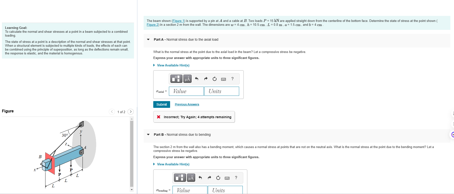
The beam shown Figure is supported by a pin at A and a cable at B Two loads PmathrmkN are applied straight down from the centerline of the bottom face. Determine the state of stress at the point shown Figure in a section m from the wall. The dimensions are wmathrm~cm hmathrm~cm Lmathrm~m amathrm~cm and bmathrm~cm
Learning Goal:
To calculate the normal and shear stresses at a point in a beam subjected to a combined loading.
The state of stress at a point is a description of the normal and shear stresses at that point When a structural element is subjected to multiple kinds of loads, the effects of each can be combined using the principle of superposition, as long as the deflections remain small, the response is elastic, and the material is homogenous.
Figure
Incorrect; Try Again; attempts remaining
Part B Normal stress due to bending
The section m from the wall also has a bending moment, which causes a normal stress at points that are not on the neutral axis. What is the normal stress at the point due to the bending moment? Let a compressive stress be negative.
Express your answer with appropriate units to three significant figures.
View Available Hints Part C Shear stress
The shear force in the beam is also not zero m from the wall. What is the magnitude of the shear stress in the x y plane at the given point? Express your answer with appropriate units to three significant figures.
View Available Hints
tau
Incorrect; Try Again; attempts remaining
Step by Step Solution
There are 3 Steps involved in it
1 Expert Approved Answer
Step: 1 Unlock

Question Has Been Solved by an Expert!
Get step-by-step solutions from verified subject matter experts
Step: 2 Unlock
Step: 3 Unlock