

Question: The block diagram below shows the interface for a Run-Length Encoder chip. The chip is initially reset to the idle state by asserting the synchronous
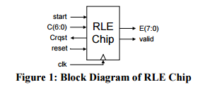
The block diagram below shows the interface for a Run-Length Encoder chip. The chip is initially reset to the idle state by asserting the synchronous reset signal. The encoding process begins when start is asserted, and ends when start is deasserted. A new character is read on port C every rising edge of clk when Crqst and start are asserted, starting with the first character of the file to be encoded. If a particular character occurs consecutively 3 or more times, then this subsequence is replaced by one occurrence of the character, followed immediately by the count, CNT, of the character, otherwise, the characters are output unchanged. Both characters and counts are output on port E, with E(7) = 0 denoting a character and E(7) = 1 denoting a count. valid is asserted when either a character or count is output. If more than 127 consecutive like characters occur, the output sequence should be the character followed by two or more counts (e.g., 230 occurrences of 56h would be output as 56h, FFh, E7h).
Example: Input Sequence (hexadecimal format): 0A, 14, 14, 14, 14, 14, 14, 14, 56, 56, 56, 56, 56, 32, 32, 07 Output Sequence (hexadecimal format): 0A, 14, 87, 56, 85, 32, 32, 07
Question: Design the datapath and ASM, explicitly showing reset, for the Run-Length Encoder, ensuring that it achieves maximum throughput.
start RLE C(6:0) E(7:0) rgst Chip valid clk Figure 1 Block Diagram of RLE Chip
Step by Step Solution
There are 3 Steps involved in it

Get step-by-step solutions from verified subject matter experts