

Question: The circuit in Figure 2 is operating in the sinusoidal steady state. 592 10 4mF W is ia 5mH 2.5mH iz 2592 v(t) 2092
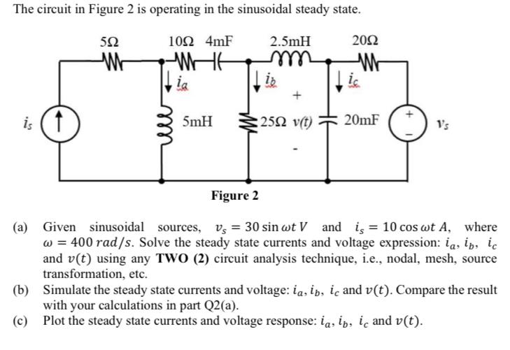
The circuit in Figure 2 is operating in the sinusoidal steady state. 592 10 4mF W is ia 5mH 2.5mH iz 2592 v(t) 2092 W ic 20mF +1 Vs Figure 2 (a) Given sinusoidal sources, v, 30 sin wt V and is = 10 cos wt A, where w = 400 rad/s. Solve the steady state currents and voltage expression: ia, ip, ic and v(t) using any TWO (2) circuit analysis technique, i.e., nodal, mesh, source transformation, etc. (b) Simulate the steady state currents and voltage: ia, ip, i and v(t). Compare the result with your calculations in part Q2(a). (c) Plot the steady state currents and voltage response: ias ip, i and v(t).
Step by Step Solution
There are 3 Steps involved in it

Get step-by-step solutions from verified subject matter experts