

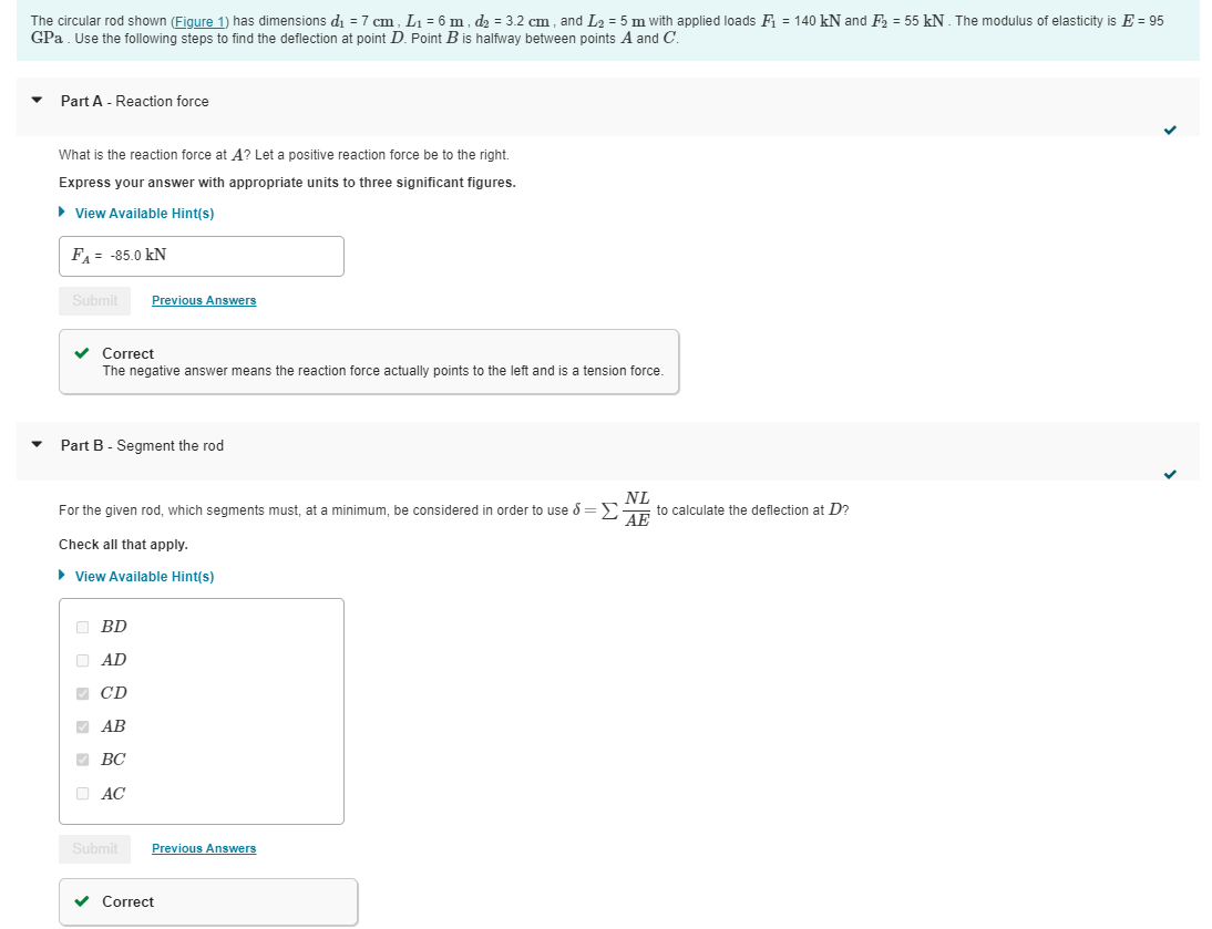
Question: The circular rod shown ( Figure 1 ) has dimensions d 1 = 7 c m , L 1 = 6 m , d 2
The circular rod shown Figure has dimensions and with applied loads and The modulus of elasticity is
GPa Use the following steps to find the deflection at point Point is halfway between points A and
Part A Reaction force
What is the reaction force at Let a positive reaction force be to the right.
Express your answer with appropriate units to three significant figures.
View Available Hints
Correct
The negative answer means the reaction force actually points to the left and is a tension force.
Part B Segment the rod
For the given rod, which segments must, at a minimum, be considered in order to use to calculate the deflection at
Check all that apply.
View Available Hints
Correct Part C Calculate the deflection
What is the deflection of the end of the rod, Let a positive deflection be to the right.
Express your answer with appropriate units to three significant figures.
View Available Hints
Incorrect; Try Again Learning Goal:
To calculate the elastic deflection in an axially loaded member.
For a bar subject to axial loading, the change in length, or deflection, between
two points A and is where is the internal normal
force, is the crosssectional area, is the modulus of elasticity of the
material, is the original length of the bar, and is the position along the bar.
This equation applies as long as the response is linear elastic and the cross
section does not change too suddenly.
In the simpler case of a constant cross section, homogenous material, and
constant axial load, the integral can be evaluated to give This shows
that the deflection is linear with respect to the internal normal force and the
length of the bar.
In some situations, the bar can be divided into multiple segments where each
one has uniform internal loading and properties. Then the total deflection can be
written as a sum of the deflections for each part,
Step by Step Solution
There are 3 Steps involved in it
1 Expert Approved Answer
Step: 1 Unlock

Question Has Been Solved by an Expert!
Get step-by-step solutions from verified subject matter experts
Step: 2 Unlock
Step: 3 Unlock