

Question: The compressor and engine shown are supported by two identical 6 x 2.034-inch channel beams composed of 1010 HR Steel with a hot-rolled surface finish.
The compressor and engine shown are supported by two identical 6 x 2.034-inch channel beams composed of 1010 HR Steel with a hot-rolled surface finish. When the compressor is running, the vibrational amplitude is measured with a dial indicator at the center of the span of the channels. The table below gives the maximum and minimum readings of the dial indicator for three different combinations of engine and compressor that can be mounted to this skid. Also shown in the table are the static weights of the compressor and engine.
| Case | compressor weight | engine weight | minimum reading | maximum reading |
| 1 | 985 lb | 1385 lb | 0.403 in | 0.605 in |
| 2 | 725 lb | 930 lb | 0.213 in | 0.491 in |
| 3 | 565 lb | 710 lb | 0.102 in | 0.44 in |
Find the beam's equivalent diameter for the Marin size factor. Then find the beam's fully-corrected endurance strength.
de==
Se==
For each case, find the midrange and alternating stresses in each beam at the most critical location. Also find the factor of safety against 1st-cycle yielding (Langer failure criteria). Then find fatigue factor of safety with Goodman, Gerber, and ASME-Elliptic failure criteria.
Assume: -the channels are mounted such that stress concentrations are neligible. -self-weight of the channels may be also be neglected. -all deflection measured by the dial indicator is a result of flexure of the channels. -the dynamic deflection measured by the dial indicator is caused by equal dynamic forces applied at the respective mounting points of the engine and the compressor. -the centers of gravity of the engine and the compressor are directly above their respective mounting points.
| Case | m | a | ny | nf,Goodman, | nf,Gerber, | nf,ASME, |
| 1 | ||||||
| 2 | ||||||
| 3 |
On alternating-midrange stress axes, plot the load lines implied by each of the loading cases given, along with the three fatigue failure envelopes and the Langer line.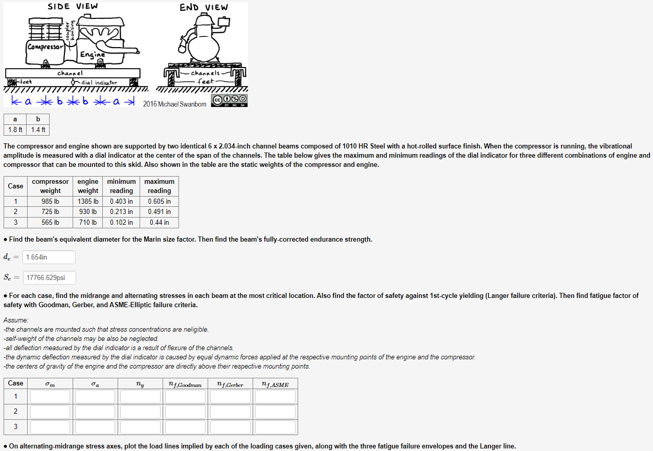 THE d_e AND Se VALUES IN THE IMAGE ARE ALREADY CORRECT IF THAT HELPS!
The compressor and engine shown are supported by two identical 62.034-inch channel beams composed of 1010HR Steel with a hot-rolled surface finish. When the compressor is running, the vibrational amplitude is measured with a dial indicator at the center of the span of the channels. The table below gives the maximum and minimum readings of the dial indicator for three different combinations of engine anc compressor that can be mounted to this skid. Also shown in the table are the static weights of the compressor and engine. - Find the beam's equivalent diameter for the Marin size factor. Then find the beam's fully-corrected endurance strength. de= Se= - For each case, find the midrange and alternating stresses in each beam at the most critical location. Also find the factor of safety against 1 st-cycle yielding (Langer failure criteria). Then find fatigue factor of safety with Goodman, Gerber, and ASME-Elliptic failure criteria. Assume: -the channels are mounted such that stress concentrations are neligible. -self-weight of the channels may be also be neglected. -all deflection measured by the dial indicator is a result of flexure of the channels. -the dynamic deflection measured by the dial indicator is caused by equal dynamic forces applied at the respective mounting points of the engine and the compressor. -the centers of gravity of the engine and the compressor are directly above their respective mounting points
Step by Step Solution
There are 3 Steps involved in it

Get step-by-step solutions from verified subject matter experts