

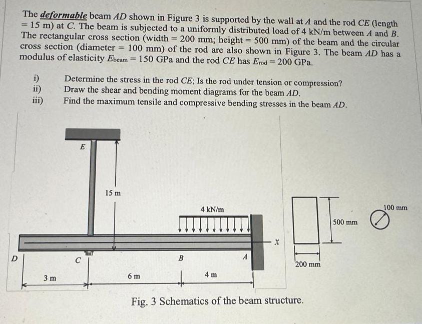
Question: The deformable beam A D shown in Figure 3 is supported by the wall at A and the rod C E ( length = 1
The deformable beam shown in Figure is supported by the wall at A and the rod length
at The beam is subjected to a uniformly distributed load of between A and
The rectangular cross section width ; height of the beam and the circular
cross section diameter of the rod are also shown in Figure The beam has a
modulus of elasticity GPa and the rod has GPa.
i Determine the stress in the rod ; Is the rod under tension or compression?
ii Draw the shear and bending moment diagrams for the beam
iii Find the maximum tensile and compressive bending stresses in the beam
Fig. Schematics of the beam structure. Cantilevered Beam Slopes and Deflections
Step by Step Solution
There are 3 Steps involved in it
1 Expert Approved Answer
Step: 1 Unlock

Question Has Been Solved by an Expert!
Get step-by-step solutions from verified subject matter experts
Step: 2 Unlock
Step: 3 Unlock