

Question: The diagram shown in Figure 2 is a schematic representation of a film blowing die. iii. Stating your assumptions clearly, show that the velocity profile
The diagram shown in Figure is a schematic representation of a film blowing die. iii. Stating your assumptions clearly, show that the velocity profile for polymer melt
A can be written as:
where is an integration constant.
iv Assuming that no slip conditions exist on both of the stationary walls of the
annulus, show that
and hence that the velocity profile can be written as
v For many film blowing dies, the inner and outer radii are large enough and the annular gap is small enough for curvature to be neglected: in these cases, an excellent approximation for the velocity field in the annular gap is that for flow in a parallelsided slot. A schematic diagram of such a slot is shown in Figure where the width of the slot is equal to the perimeter of the annulus.
Flow direction
Figure Approximate flow geometry for an annulus where curvature is negligible. The velocity field in a slot of this nature can be written
By making suitable substitutions for the slot half thickness, and the
coordinate in terms of and show that
vi In order to compare the velocity profiles from parts iv and v for different
amounts of curvature it is convenient to say that Use this substitution
to compare when the result from part iv should be used in preference to the
simpler result from part v You may find it useful to quantify the average
difference in the velocity fields and to base your judgement on that. Comment
on your answer in relation to practical design estimates.
vii. Describe how you would now check whether the initial assumption of the
range of shear rates likely to be encountered in the die is correct or not. You
need not do any calculations or derivations when answering this question.
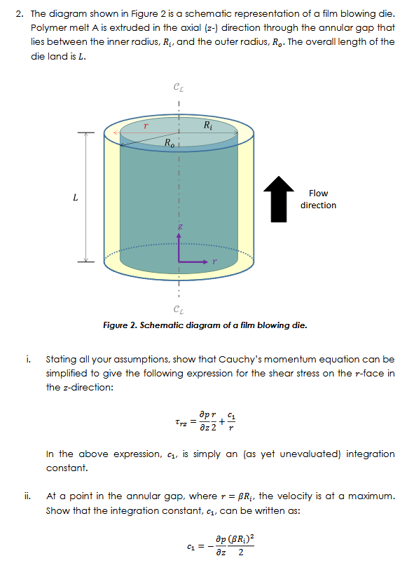
Polymer melt is extruded in the axial direction through the annular gap that
lies between the inner radius, and the outer radius, The overall length of the
die land is
Figure Schematic diagram of a film blowing die.
i Stating all your assumptions, show that Cauchy's momentum equation can be
simplified to give the following expression for the shear stress on the face in
the direction:
In the above expression, is simply an as yet unevaluated integration
constant.
ii At a point in the annular gap, where the velocity is at a maximum.
Show that the integration constant, can be written as:
Step by Step Solution
There are 3 Steps involved in it
1 Expert Approved Answer
Step: 1 Unlock

Question Has Been Solved by an Expert!
Get step-by-step solutions from verified subject matter experts
Step: 2 Unlock
Step: 3 Unlock