

Question: The Figure 1 depicts a simple three phase AC machine with a stator consisting of three separate windings spaced 120 electrical degrees apart around
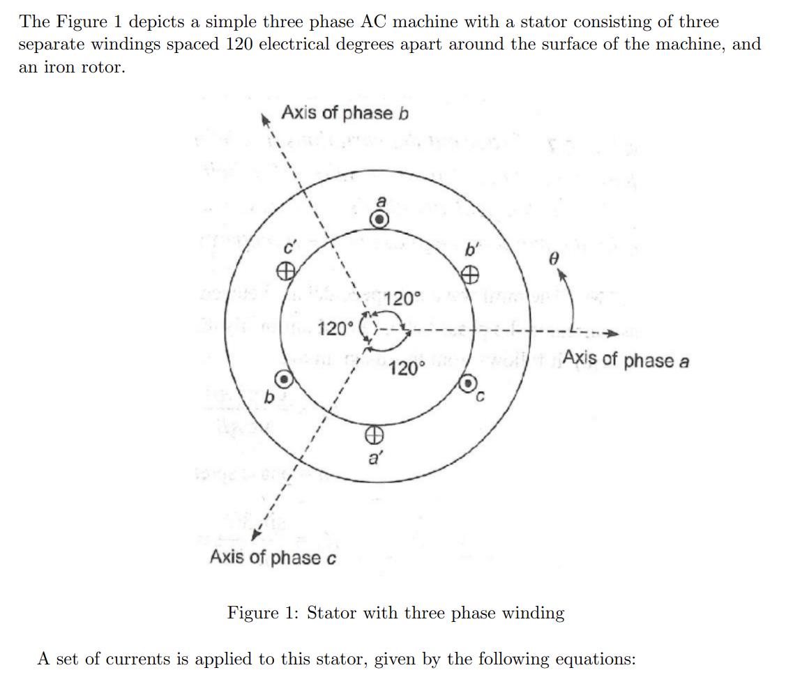
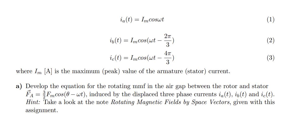
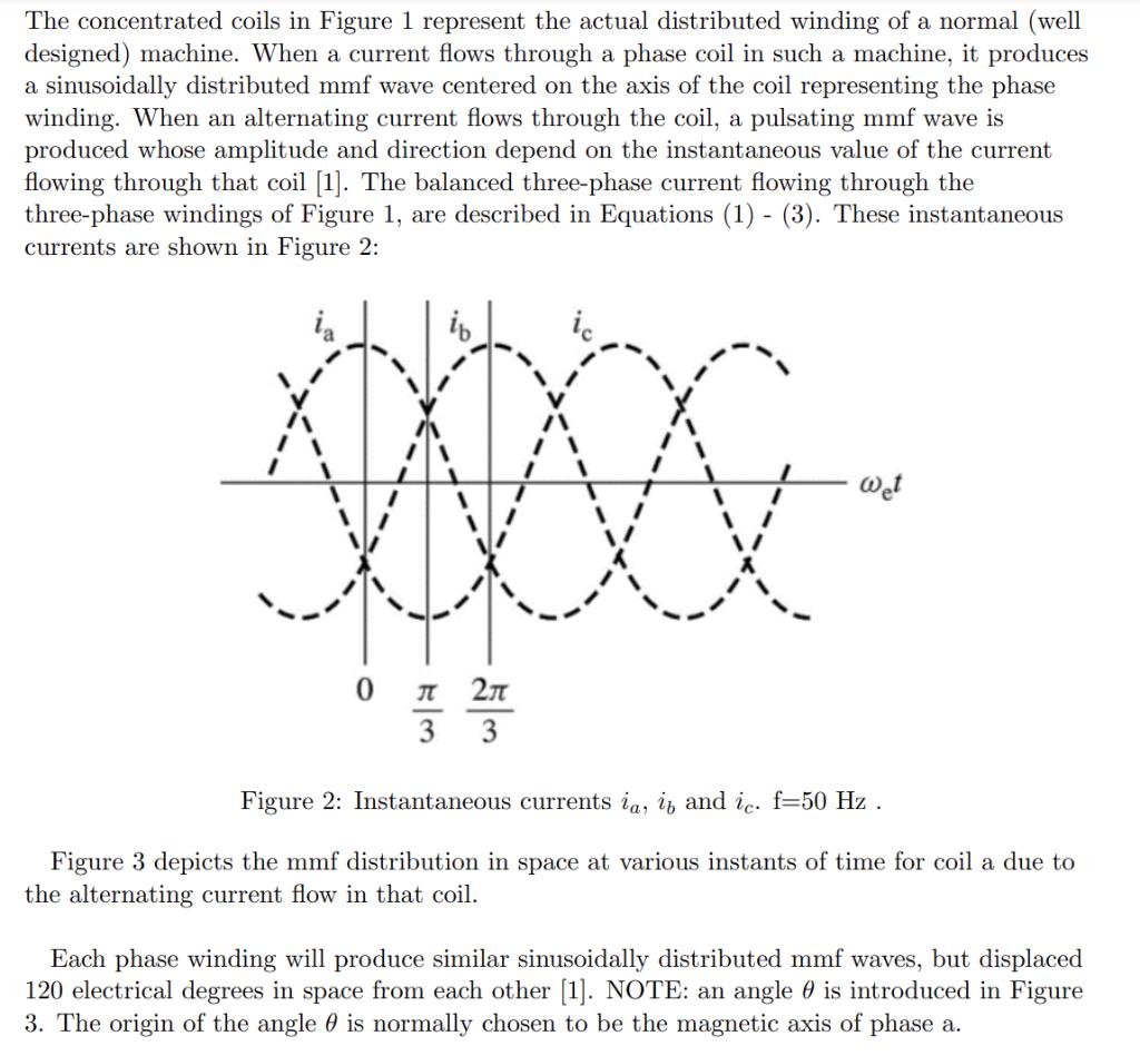
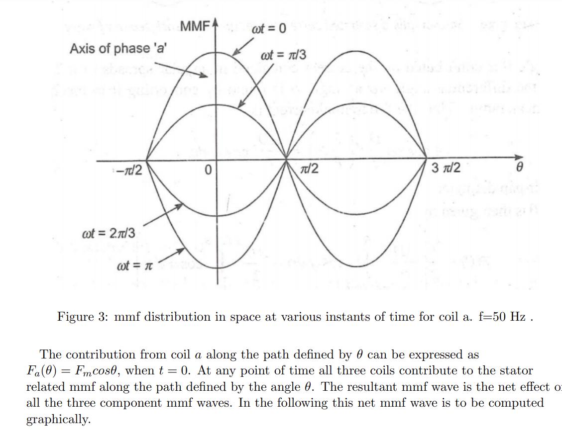
The Figure 1 depicts a simple three phase AC machine with a stator consisting of three separate windings spaced 120 electrical degrees apart around the surface of the machine, and an iron rotor. Axis of phase b O 120 Axis of phase c 1 120 a' 120 0 Axis of phase a Figure 1: Stator with three phase winding A set of currents is applied to this stator, given by the following equations: ia(t) = Imcoswt 2T if(t) = Imcos (wt 3 47 ic(t) = Imcos (wt 3 where Im [A] is the maximum (peak) value of the armature (stator) current. (1) (2) (3) a) Develop the equation for the rotating mmf in the air gap between the rotor and stator FA= Fmcos (0-wt), induced by the displaced three phase currents ia(t), iz(t) and ic(t). Hint: Take a look at the note Rotating Magnetic Fields by Space Vectors, given with this assignment. The concentrated coils in Figure 1 represent the actual distributed winding of a normal (well designed) machine. When a current flows through a phase coil in such a machine, it produces a sinusoidally distributed mmf wave centered on the axis of the coil representing the phase winding. When an alternating current flows through the coil, a pulsating mmf wave is produced whose amplitude and direction depend on the instantaneous value of the current flowing through that coil [1]. The balanced three-phase current flowing through the three-phase windings of Figure 1, are described in Equations (1)-(3). These instantaneous currents are shown in Figure 2: ib XXXXXX 0 553 2 3 Wet Figure 2: Instantaneous currents ia, it and ic. f=50 Hz . Figure 3 depicts the mmf distribution in space at various instants of time for coil a due to the alternating current flow in that coil. Each phase winding will produce similar sinusoidally distributed mmf waves, but displaced 120 electrical degrees in space from each other [1]. NOTE: an angle is introduced in Figure 3. The origin of the angle is normally chosen to be the magnetic axis of phase a. Axis of phase 'a' -T2 wot = 2.7/3 wt = MMFA 0 wt = 0 wt = /3 /2 3 /2 Figure 3: mmf distribution in space at various instants of time for coil a. f=50 Hz . The contribution from coil a along the path defined by can be expressed as Fa(0) = Fmcos0, when t = 0. At any point of time all three coils contribute to the stator related mmf along the path defined by the angle 0. The resultant mmf wave is the net effect o all the three component mmf waves. In the following this net mmf wave is to be computed graphically. b) At instant t = 0: Sketch the mmf of each armature coil for this instant, and the resulting armature mmf. Use for instance a figure similar to Figure 1 for your sketch. Comment the results. In addition, make a sketch of the ("unfolded") stator to form a horizontal machine similar to Figure 3, including all three phases/coils with their respective mmf waves (the fundamental). c) Make a similar sketch as Figure 1 for t = 5 ms. Comment. (You are not required to draw the "unfolded" variant in this or the following exercises.) d) Make a similar sketch for t= 10 ms. Comment. e) Make a similar sketch for t = 15 ms. Comment. f) Make an overall comment on exercise a) to d).
Step by Step Solution
3.44 Rating (173 Votes )
There are 3 Steps involved in it
Solution As per ... View full answer

Get step-by-step solutions from verified subject matter experts