

Question: The first-order RL network in Figure 2 has been at rest for a long period of time with switches S and S in the
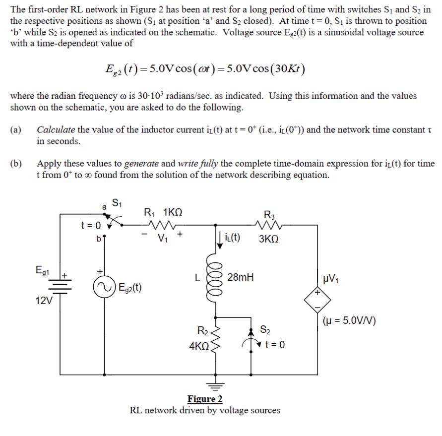
The first-order RL network in Figure 2 has been at rest for a long period of time with switches S and S in the respective positions as shown (S at position 'a' and S closed). At time t = 0, S is thrown to position 'b' while S2 is opened as indicated on the schematic. Voltage source Eg2(t) is a sinusoidal voltage source with a time-dependent value of Eg2 (t)=5.0V cos(at) = 5.0V cos (30Kt) where the radian frequency w is 30-10 radians/sec. as indicated. Using this information and the values shown on the schematic, you are asked to do the following. (a) (b) Calculate the value of the inductor current i(t) at t= 0+ (i.e., iL(0)) and the network time constant t in seconds. Apply these values to generate and write fully the complete time-domain expression for i(t) for time t from 0 to found from the solution of the network describing equation. Eg1 HILE 12V t = 0 S ~ Egz(t) R1 1 ww V L elle R 4KQ il(t) 28mH R3 ww 3KQ S t = 0 Figure 2 RL network driven by voltage sources + V ( = 5.0V/V)
Step by Step Solution
3.33 Rating (159 Votes )
There are 3 Steps involved in it
Part a Calculating initial inductor current iL0 and network time constant Initial inductor current A... View full answer

Get step-by-step solutions from verified subject matter experts