

Question: The following control inputs are active in the bus system, for each case, specify the register transfer that will be executed during the next transition.
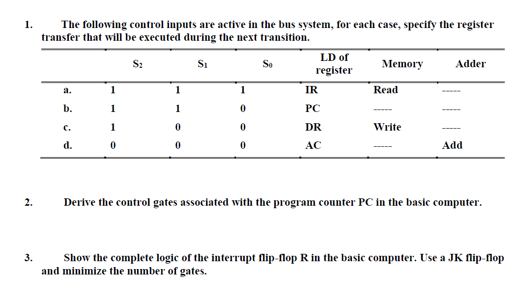
The following control inputs are active in the bus system, for each case, specify the register transfer that will be executed during the next transition.
tabletableLD ofregisterMemory,AdderaIRRead,bPCcDRWrite,dAdd
Derive the control gates associated with the program counter PC in the basic computer.
Show the complete logic of the interrupt flipflop in the basic computer. Use a JK flipflop and minimize the number of gates.
I hope to solve all branches of the question and draw the required step by step
Step by Step Solution
There are 3 Steps involved in it
1 Expert Approved Answer
Step: 1 Unlock

Question Has Been Solved by an Expert!
Get step-by-step solutions from verified subject matter experts
Step: 2 Unlock
Step: 3 Unlock