

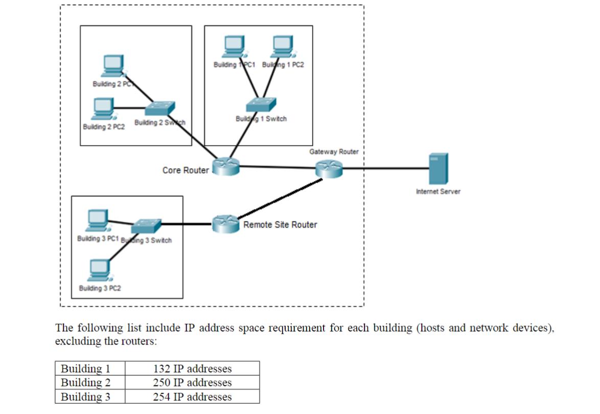
The following diagram shows the topology of a corporate network consisting of three buildings. Each building contains
Question:
The following diagram shows the topology of a corporate network consisting of three buildings. Each building contains a number of PCs and a switched LAN.
Two buildings are connected to a core router, which is connected to a Gateway router. A remote site (Building
3) is connected to a remote site router that is connected separately to the Gateway router. The Gateway router has a single connection to an Internet server with IP address 108.0.0.1. The link between the Gateway router and the Internet server uses the subnet 108.0.0.0/30. You can find the network map in the following image with extra information:
VLSM is implemented. In order to determine the base network address for each building, use your and your partner's student ID numbers for the buildings in the following way:
1. Create an IP address in form of 100.92.20.99 from it, and calculate the network address associated with this IP address and the corresponding subnet mask for Building 1 for accommodating the hosts in Building 1.
2. Do the same for Building 2, where the IP address in this case is: 100.92.20.91 instead of 100.92.20.99
3. For building 3, assign all addresses from the 192.168.0.0 range with the appropriate subnet mask.
4. Choose private IP addresses of your choice for the connection between the routers
Expert Answer:


Microeconomics
ISBN: 978-0321866349
14th canadian Edition
Authors: Christopher T.S. Ragan, Richard G Lipsey
