

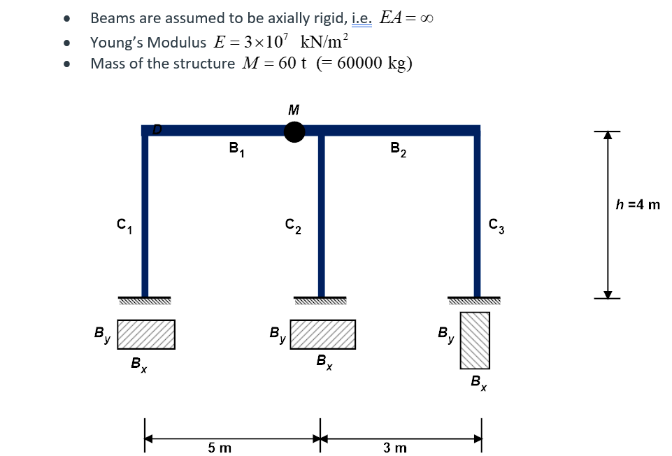
Question: The following figure shows a simple 2 D frame structure. C 1 , C 2 and C 3 indicate the columns, B 1 and B
The following figure shows a simple D frame structure. C C and C indicate the columns, B and B the beams and M the total mass of the frame. The total mass of the frame is assumed to be concentrated at a single point as shown. The dimensions of column and beam member are assigned differently to each student in the following table. The crosssectional views are shown under each column member.
Beams are assumed to be axially rigid, ie
Youngs Modulus
Beams are assumed to be axially rigid, ie
Young's Modulus
Mass of the structure Again, the total mass of the frame is assumed to be concentrated at floor level and beams are assumed
to be axially rigid ie Such a model is referred to as shear building and lateral stiffness of the
building is given by
where is the Young's Modulus, I the moment of inertia of column cross section and the height of
column. Based on the formula and following data, determine the natural period of the building
C Bxcm By cm
C Bxcm Bycm
C Bxcm Bycm
Beams bwcm hcm
Step by Step Solution
There are 3 Steps involved in it
1 Expert Approved Answer
Step: 1 Unlock

Question Has Been Solved by an Expert!
Get step-by-step solutions from verified subject matter experts
Step: 2 Unlock
Step: 3 Unlock